Dodge Caliber. Manual - part 79


  Index      Dodge     Dodge Caliber - service repair manual 2007 year


Search            


Content   ..  77  78  79  80   ..


Dodge Caliber. Manual - part 79


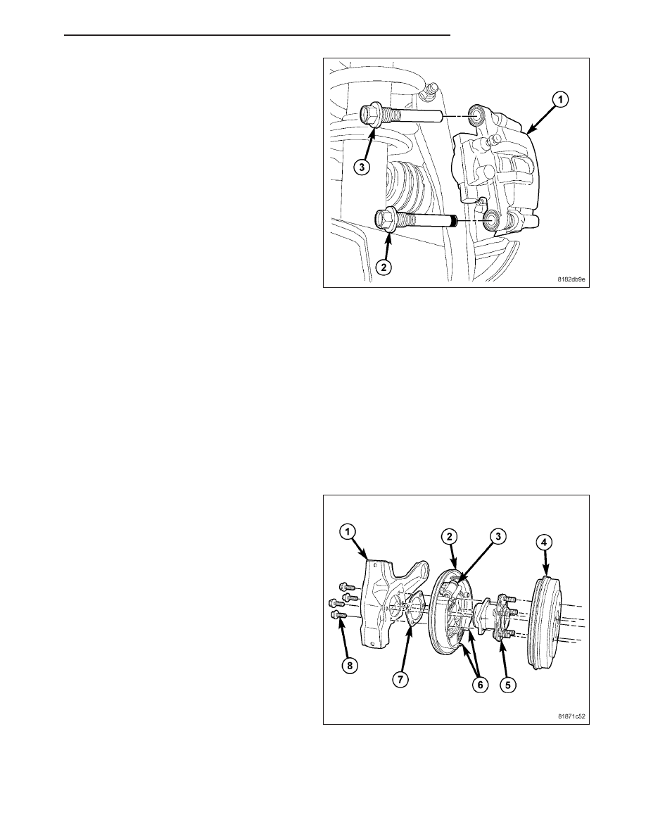
At each rear brake caliper (1) this bolt (2) is placed at
the lower location.

Front disc brakes are equipped with an audible wear indicator on the right side inboard brake pad only. The left side
pads do not include an audible wear indicator.

Rear disc brakes are equipped with audible wear indicators on both left side and right side inboard brake pads.

When the brake pads are replaced, only brake pads meeting the Original Equipment Manufacturer (OEM) formula-
tion (such as Mopar

T

replacement parts) should be used.

All brake rotors are fully coated with zinc dust, water-soluble, environmentally friendly corrosion preventive. Both the
friction surfaces and the vents are coated. During initial brake applications of a new rotor, the brake pads scrub the
coating off the friction surfaces, ensuring that the remainder will be rust free. Coating the vents also ensures that
there will not be a loss of heat capacity over time.

REAR DRUM BRAKES

All rear drum brake equipped vehicles feature 9 inch (229 mm) rear drum brakes. The drum brakes are all two-shoe
(7), internal-expanding type with an automatic adjuster screw.

Each rear drum brake consists of these major compo-
nents as well as the attaching hardware:

Adjuster

Drum (4)

Shoes (6)

Support Plate (2)

Wheel Cylinder (3)

The rear drum brakes also serve as part of the parking brake system. (Refer to 5 - BRAKES/PARKING BRAKE -
DESCRIPTION)

PM

BRAKES - BASE

5 - 17

DIAGNOSIS AND TESTING

DRUM BRAKE AUTOMATIC ADJUSTER

To properly test the drum brake automatic adjuster, the aide of a helper inside the vehicle to apply the brakes will
be necessary.

1. Raise and support the vehicle. (Refer to LUBRICATION & MAINTENANCE/HOISTING - STANDARD PROCE-

DURE).

2. Remove the access plug from the rear adjustment slot in each brake support plate.

3. Insert a thin screwdriver in the adjustment slot and push back the adjustment lever. With the lever in this posi-

tion, back the star wheel adjustment off approximately 10 notches. This will eliminate the possibility that the
brake is at full adjustment, and can be adjusted no further.

4. Remove the screwdriver from the adjustment slot.

5. Watch the star wheel through the adjustment slot, while a helper applies the brake pedal. As the brake shoes

apply, the adjustment lever should move downward, turning the star wheel. A definite rotation of the adjuster star
wheel can be observed if the automatic adjuster is working properly.

If the star wheel does not move as indicated, the brake drum needs to be removed and further inspection of the
rear brakes is necessary.

6. If the star wheel is operating properly, readjust the brakes. (Refer to 5 - BRAKES/HYDRAULIC/MECHANICAL/

BRAKE PADS/SHOES - ADJUSTMENTS).

7. Reinstall the adjustment slot access plug.

8. Lower the vehicle.

5 - 18

BRAKES - BASE

PM

PADS-FRONT BRAKE

REMOVAL

NOTE: Before proceeding, (Refer to 5 - BRAKES - WARNING) (Refer to 5 - BRAKES - CAUTION).

1. Raise and support the vehicle. (Refer to LUBRICATION & MAINTENANCE/HOISTING - STANDARD PROCE-

DURE)

NOTE: Perform Step 2 through Step 5 on each side of the vehicle to complete pad set removal.

2. Remove the wheel mounting nuts (3), then the tire

and wheel assembly (1).

CAUTION: When removing the caliper guide pin
bolts (2, 3) note that one (upper) has a special
sleeve on the end. It important that his bolt be
installed in the upper mounting hole when the cal-
iper is installed.

3. Remove the two brake caliper guide pin bolts (2,

3).

4. Remove the disc brake caliper (4) from the disc

brake adapter bracket (1) and hang it out of the
way using wire or a bungee cord. Use care not to
overextend the brake hose when doing this.

PM

BRAKES - BASE

5 - 19

5. Remove the brake pads (4, 5) from the caliper

adapter bracket (2).

CLEANING

WARNING: Dust and dirt accumulating on brake parts during normal use may contain asbestos fibers from
production or aftermarket brake linings. Breathing excessive concentrations of asbestos fibers can cause
serious bodily harm. Exercise care when servicing brake parts. Do not sand or grind brake lining unless
equipment used is designed to contain the dust residue. Do not clean brake parts with compressed air or
by dry brushing. Cleaning should be done by dampening the brake components with a fine mist of water,
then wiping the brake components clean with a dampened cloth. Dispose of cloth and all residue containing
asbestos fibers in an impermeable container with the appropriate label. Follow practices prescribed by the
Occupational Safety And Health Administration (OSHA) and the Environmental Protection Agency (EPA) for
the handling, processing, and disposing of dust or debris that may contain asbestos fibers.

INSPECTION

Visually inspect brake pads for uneven lining wear. Also inspect for excessive lining deterioration. Check the clear-
ance between the tips of the wear indicators (if equipped) on the pads and the brake rotors.

If a visual inspection does not adequately determine the condition of the lining, a physical check will be necessary.
To check the amount of lining wear, remove the disc brake pads from the vehicle.

Measure brake pad minimum thickness. Brake pads must be replaced when usable material on a brake pad lining
measured at its thinnest point measures one millimeter (0.04 inches) or less.

NOTE: It is important to inspect both front and rear brake pads during the same inspection. Typically, front
and rear brake pads wear out at the same time.

Replace both disc brake pads (inboard and outboard) at each caliper. It is also necessary to replace the pads on
the opposite side of the vehicle as well as the pads failing inspection to maintain proper braking characteristics.

If the brake pad assemblies do not require replacement, be sure to reinstall the brake pads in the original position
they were removed from.

INSTALLATION

NOTE: Perform Step 1 through Step 5 on each side of the vehicle to complete pad set installation, then
proceed to Step 6.

NOTE: Make sure that the audible wear indicators (if equipped) are placed toward the top when the inboard
brake pads are installed on each side of the vehicle.

5 - 20

BRAKES - BASE

PM


Content   ..  77  78  79  80   ..