Dodge Durango (DN). Manual - part 323
 

  Index      Dodge     Dodge Durango (DN) - service repair manual 2000 year


Search            


Content   ..  321  322  323  324   ..


Dodge Durango (DN). Manual - part 323


(5) Disengage the overhead console wire harness

connector from the mount on the paperclip by push-
ing the connector firmly toward the left side of the
overhead console housing.

(6) Remove the paperclip from the overhead con-

sole housing.

INSTALLATION

(1) Position the paperclip onto the overhead con-

sole housing.

(2) Engage the overhead console wire harness con-

nector onto the mount on the paperclip by aligning
the channels on the connector with the tab on the
mount and pushing the connector firmly toward the
right side of the overhead console housing.

(3) Install and tighten the four screws that secure

the paperclip to the overhead console housing.
Tighten the screws to 2.2 N·m (20 in. lbs.).

(4) Install the overhead console onto the headliner.

Refer to Overhead Console in the Removal and
Installation section of this group for the procedures.

(5) Reconnect the battery negative cable.

COMPASS MINI-TRIP COMPUTER

REMOVAL

(1) Disconnect and isolate the battery negative

cable.

(2) Remove the overhead console from the head-

liner. Refer to Overhead Console in the Removal
and Installation section of this group for the proce-
dures.

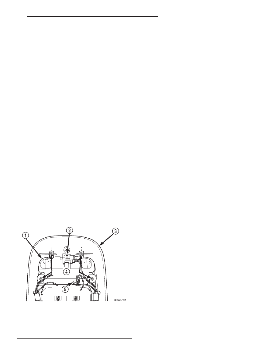
(3) Remove the four screws that secure the com-

pass mini-trip computer module to the overhead con-
sole housing (Fig. 7).

(4) Pull the compass mini-trip computer module

away from the overhead console far enough to access
the wire harness connectors.

(5) Disengage the overhead console wire harness

connector from the mount on the compass mini-trip
computer module housing by pushing the connector
firmly toward the left side of the overhead console
housing.

(6) Disconnect the overhead console wire harness

connector from the compass mini-trip computer mod-
ule connector receptacle.

(7) Remove the compass mini-trip computer mod-

ule from the overhead console housing.

INSTALLATION

(1) Position the compass mini-trip computer mod-

ule onto the overhead console housing.

(2) Reconnect the overhead console wire harness

connector to the compass mini-trip computer module
connector receptacle.

(3) Engage the overhead console wire harness con-

nector onto the mount on the compass mini-trip com-
puter module housing by aligning the channels on
the connector with the tab on the mount and pushing
the connector firmly toward the right side of the
overhead console housing.

(4) Install and tighten the four screws that secure

the compass mini-trip computer module to the over-
head console housing. Tighten the screws to 2.2 N·m
(20 in. lbs.).

(5) Install the overhead console onto the headliner.

Refer to Overhead Console in the Removal and
Installation section of this group for the procedures.

(6) Reconnect the battery negative cable.

NOTE: If a new compass mini-trip computer has
been installed, the compass will have to be cali-
brated and the variance set. Refer to Compass Vari-
ation Adjustment and Compass Calibration in the
Service Procedures section of this group for the
procedures.

OVERHEAD CONSOLE READING AND
COURTESY LAMP HOUSING

REMOVAL

(1) Disconnect and isolate the battery negative

cable.

(2) Remove the compass mini-trip computer mod-

ule from the overhead console housing. Refer to
Compass Mini-Trip Computer in the Removal and
Installation section of this group for the procedures.

Fig. 7 Compass Mini-Trip Computer Remove/Install

1 – COMPASS MINI-TRIP COMPUTER MODULE
2 – OVERHEAD CONSOLE WIRE HARNESS CONNECTOR
3 – OVERHEAD CONSOLE HOUSING
4 – SCREW (4)
5 – COMPUTER CONNECTOR

DN

OVERHEAD CONSOLE SYSTEMS

8V - 11

REMOVAL AND INSTALLATION (Continued)

(3) Remove the two screws that secure the reading

and courtesy lamp housing to the overhead console
housing (Fig. 8).

(4) Pull the reading and courtesy lamp housing

away from the overhead console housing far enough
to turn it over for access to the lamp bulbs.

(5) Remove both reading and courtesy lamp bulbs

from their bulb holders by pulling them straight out
from the holders.

(6) Remove both switches from their mounting

slots by sliding them towards their respective out-
board ends of the reading and courtesy lamp housing.

(7) Remove the four bulb holders from their

mounting holes in the reading and courtesy lamp
housing by depressing the latch on each side of each
holder and pushing the bulb side of the holder out
through the wire side of the mounting hole.

(8) Remove the reading and courtesy lamp housing

from the overhead console housing.

INSTALLATION

(1) Install each of the four bulb holders into their

mounting holes in the reading and courtesy lamp
housing by inserting the bulb side of the holder into
the wire side of the mounting hole and pushing it
through the mounting hole until both latches are
engaged with the lamp housing.

(2) Install both switches into their mounting slots

by sliding them inboard from their respective ends of

the reading and courtesy lamp housing until they
snap into place.

(3) Install both reading and courtesy lamp bulbs

into their bulb holders by pushing them straight into
the holders.

(4) Position the reading and courtesy lamp housing

onto the overhead console housing. Be certain that
the sunglasses storage bin damper spring is engaged
in the slot on the rear flange of the reading and cour-
tesy lamp housing.

(5) Install and tighten the two screws that secure

the reading and courtesy lamp housing to the over-
head console housing. Tighten the screws to 2.2 N·m
(20 in. lbs.).

(6) Install the compass mini-trip computer module

into the overhead console housing. Refer to Compass
Mini-Trip Computer 
in the Removal and Installa-
tion section of this group for the procedures.

(7) Reconnect the battery negative cable.

SUNGLASSES STORAGE BIN

REMOVAL

(1) Disconnect and isolate the battery negative

cable.

(2) Remove the reading and courtesy lamp housing

from the overhead console. Refer to Overhead Con-
sole Reading and Courtesy Lamp Housing 
in the
Removal and Installation section of this group for the
procedures.

(3) Unlatch and remove the sunglasses storage bin

from the overhead console housing.

INSTALLATION

(1) Position the sunglasses storage bin into the

overhead console housing.

(2) Engage the latch of the sunglasses storage bin

with the latch striker on the rear of the storage bin
opening in the overhead console housing.

(3) Be certain that the sunglasses storage bin pivot

shaft is located in the two pivot receptacles just
behind the reading and courtesy lamp lenses in the
overhead console housing.

(4) Be certain that the sunglasses storage bin

damper spring is installed on the pivot shaft with the
two end tabs of the spring engaged with the flats on
the rear of the shaft, and the center tab engaged over
the front of the shaft.

(5) Install the reading and courtesy lamp housing

onto the overhead console. Refer to Overhead Con-
sole Reading and Courtesy Lamp Housing 
in the
Removal and Installation section of this group for the
procedures.

(6) Reconnect the battery negative cable.

Fig. 8 Overhead Console Reading and Courtesy

Lamp Housing Remove/Install

1 – COMPASS MINI-TRIP COMPUTER
2 – SLOT
3 – SUNGLASSES STORAGE BIN DAMPER SPRING
4 – OVERHEAD CONSOLE READING AND COURTESY LAMP

HOUSING

5 – SCREWS (2)
6 – BULB HOLDERS
7 – SWITCHES

8V - 12

OVERHEAD CONSOLE SYSTEMS

DN

REMOVAL AND INSTALLATION (Continued)

GARAGE DOOR OPENER STORAGE BIN DOOR

REMOVAL

(1) Disconnect and isolate the battery negative

cable.

(2) Remove the overhead console from the head-

liner. Refer to Overhead Console in the Removal
and Installation section of this group for the proce-
dures.

(3) Remove the two screws that secure the garage

door opener storage bin door pivot and bumper block
to the overhead console housing (Fig. 9).

(4) Remove the garage door opener storage bin

door pivot and bumper block from the overhead con-
sole housing.

(5) Unlatch and remove the garage door opener

storage bin door from the overhead console housing.

INSTALLATION

(1) Position the garage door opener storage bin

door into the overhead console housing.

(2) Engage the latch of the garage door opener

storage bin door with the latch striker on the rear of
the storage bin opening in the overhead console hous-
ing.

(3) Be certain that both garage door opener stor-

age bin door pivot pins are located in the two pivot
receptacles in the overhead console housing just
behind the sunglasses storage bin.

(4) Position the garage door opener storage bin

door pivot and bumper block onto the overhead con-
sole housing.

(5) Install and tighten the two screws that secure

the garage door opener storage bin door pivot and
bumper block to the overhead console housing.
Tighten the screws to 2.2 N·m (20 in. lbs.).

(6) Install the overhead console onto the headliner.

Refer to Overhead Console in the Removal and
Installation section of this group for the procedures.

(7) Reconnect the battery negative cable.

AMBIENT TEMPERATURE SENSOR

REMOVAL

(1) Disconnect and isolate the battery negative

cable.

(2) Locate the ambient temperature sensor, on the

right side of the radiator yoke behind the grille (Fig.
10).

(3) Disconnect the wire harness connector from the

ambient temperature sensor connector receptacle.

(4) Remove the one screw that secures the ambient

temperature sensor bracket to the radiator yoke.

(5) Remove the ambient temperature sensor from

the radiator yoke.

Fig. 9 Garage Door Opener Storage Bin Door

Remove/Install

1 – SPRING CLIPS
2 – SUNGLASSES STORAGE BIN
3 – GARAGE DOOR OPENER STORAGE BIN DOOR
4 – PIVOT AND BUMPER BLOCK
5 – SCREW (2)

Fig. 10 Ambient Temperature Sensor Remove/Install

1 – YOKE
2 – CONNECTOR
3 – SCREW
4 – SENSOR

DN

OVERHEAD CONSOLE SYSTEMS

8V - 13

REMOVAL AND INSTALLATION (Continued)

INSTALLATION

(1) Position the ambient temperature sensor onto

the radiator yoke.

(2) Install and tighten the one screw that secures

the ambient temperature sensor bracket to the radi-
ator yoke. Tighten the screw to 5.6 N·m (50 in. lbs.).

(3) Reconnect the wire harness connector to the

ambient temperature sensor connector receptacle.

(4) Reconnect the battery negative cable.

SPECIAL TOOLS

OVERHEAD CONSOLE SYSTEMS

Degaussing Tool 6029

8V - 14

OVERHEAD CONSOLE SYSTEMS

DN

REMOVAL AND INSTALLATION (Continued)


Content   ..  321  322  323  324   ..