Dodge Durango (DN). Manual - part 310


  Index      Dodge     Dodge Durango (DN) - service repair manual 2000 year


Search            


Content   ..  308  309  310  311   ..


Dodge Durango (DN). Manual - part 310


If the defogger system does not operate, the prob-

lem should be isolated in the following manner:

(1) Confirm that the ignition switch is in the On

position.

(2) Ensure that the rear glass heating grid feed

and ground wires are connected to the glass. Confirm
that the ground wire has continuity to ground.

(3) Check the fuses in the Power Distribution Cen-

ter (PDC) and in the junction block. The fuses must
be tight in their receptacles and all electrical connec-
tions must be secure.

When the above steps have been completed and the

rear glass heating grid is still inoperative, one or
more of the following is faulty:

• Rear window switch pod

• Rear window grid lines (all grid lines would

have to be broken or one of the feed wires discon-
nected for the entire system to be inoperative).

If setting the defogger switch to the On position

produces a severe voltmeter deflection, check for a
short circuit between the rear window switch pod
defogger relay output and the rear glass heating grid.

REAR GLASS HEATING GRID

For circuit descriptions and diagrams, refer to

8W-48 - Rear Window Defogger in Group 8W - Wir-
ing Diagrams. To detect breaks in the grid lines, the
following procedure is required:

(1) Turn the ignition switch to the On position. Set

the defogger switch in the On position. The indicator
lamp should light. If OK, go to Step 2. If not OK, see
Defogger Switch in the Diagnosis and Testing section
of this group.

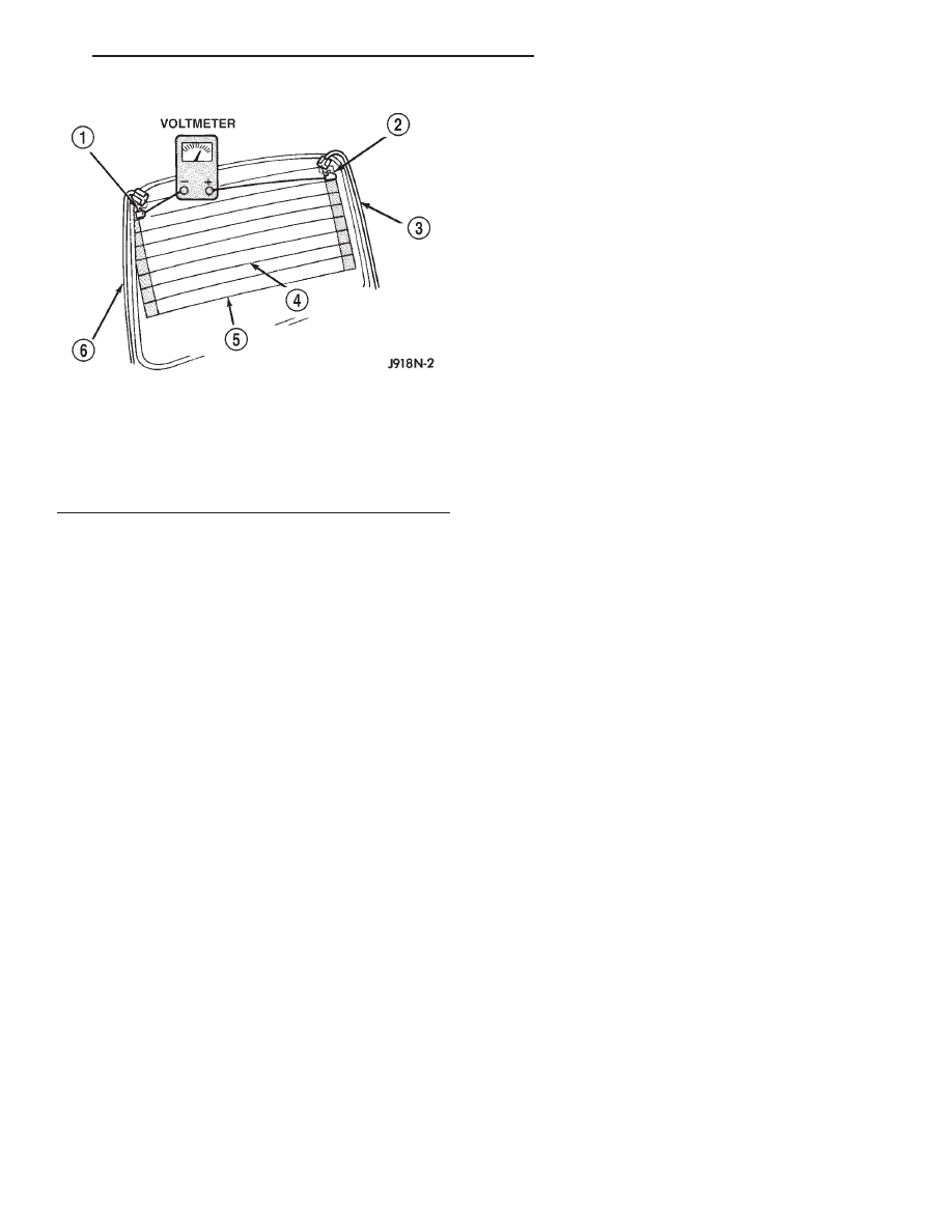
(2) Using a 12-volt DC voltmeter, contact the ver-

tical bus bar on the right side of the vehicle with the
negative lead. With the positive lead, contact the ver-
tical bus bar on the left side of the vehicle. The volt-
meter should read battery voltage. If OK, go to Step
3. If not OK, repair the open circuit to the defogger
relay as required.

(3) With the negative lead of the voltmeter, contact

a good body ground point. The voltage reading should
not change. If OK, go to Step 4. If not OK, repair the
circuit to ground as required.

(4) Connect the negative lead of the voltmeter to

the right side bus bar and touch each grid line at
midpoint C with the positive lead. A reading of
approximately six volts indicates a line is good. A
reading of zero volts indicates a break in the grid
line between midpoint C and the left side bus bar. A
reading of ten to fourteen volts indicates a break
between midpoint C and the right side bus bar. Move
the positive lead on the grid line towards the break
and the voltage reading will change as soon as the
break is crossed.

DEFOGGER SWITCH

For circuit descriptions and diagrams, refer to

8W-48 - Rear Window Defogger in Group 8W - Wir-
ing Diagrams.

WARNING: ON VEHICLES EQUIPPED WITH AIR-
BAGS,

REFER

TO

GROUP

8M

-

PASSIVE

RESTRAINT SYSTEMS BEFORE ATTEMPTING ANY
STEERING

WHEEL,

STEERING

COLUMN,

OR

INSTRUMENT PANEL COMPONENT DIAGNOSIS OR
SERVICE. FAILURE TO TAKE THE PROPER PRE-
CAUTIONS COULD RESULT IN ACCIDENTAL AIR-
BAG DEPLOYMENT AND POSSIBLE PERSONAL
INJURY.

(1) Disconnect and isolate the battery negative

cable. Remove the lower bezel from the instrument
panel and unplug the rear window switch pod wire
harness connector.

(2) Check for continuity between the ground cir-

cuit cavity of the rear window switch pod wire har-
ness connector and a good ground. There should be
continuity. If OK, go to Step 3. If not OK, repair the
open circuit as required.

(3) Connect the battery negative cable. Check for

battery voltage at the fused B(+) circuit cavity of the
rear window switch pod wire harness connector. If
OK, go to Step 4. If not OK, repair the circuit to the
Power Distribution Center (PDC) fuse as required.

(4) Turn the ignition switch to the On position.

Check for battery voltage at the fused ignition switch
output (run) circuit cavity of the rear window switch
pod wire harness connector. If OK, go to Step 5. If

Fig. 1 Rear Window Glass Grid Test

1 – TERMINAL “A”
2 – TERMINAL “B”
3 – FEED WIRE
4 – MID-POINT “C” (TYPICAL)
5 – HEATED REAR WINDOW DEFOGGER GRID
6 – GROUND WIRE

DN

ELECTRICALLY HEATED SYSTEMS

8N - 3

DIAGNOSIS AND TESTING (Continued)

not OK, repair the circuit to the junction block fuse
as required.

(5) Turn the ignition switch to the Off position.

Disconnect and isolate the battery negative cable.
Plug the wire harness connector into the rear win-
dow switch pod. Connect the battery negative cable.
Turn the ignition switch to the On position. Back
probe the rear window defogger relay output circuit
cavity of the rear window switch pod wire harness
connector. Depress and release the rear window
defogger switch. There should be battery voltage.
Depress and release the rear window defogger switch
again. There should be zero volts. If OK, go to Step 6.
If not OK, replace the faulty rear window switch pod.

(6) Depress and release the rear window defogger

switch. The rear window defogger indicator lamp
should light. If the indicator lamp does not light,
replace the bulb with a known good unit and test
again. If the lamp is still inoperative, replace the
faulty rear window switch pod.

SERVICE PROCEDURES

REAR GLASS HEATING GRID REPAIR

Repair of the rear glass heating grid lines, bus

bars, terminals or pigtail wires can be accomplished
using a Mopar Rear Window Defogger Repair Kit
(Part Number 4267922) or equivalent.

WARNING: MATERIALS

CONTAINED

IN

THE

REPAIR KIT MAY CAUSE SKIN OR EYE IRRITATION.
THE KIT CONTAINS EPOXY RESIN AND AMINE
TYPE HARDENER, WHICH ARE HARMFUL IF SWAL-
LOWED. AVOID CONTACT WITH THE SKIN AND
EYES. FOR SKIN CONTACT, WASH THE AFFECTED
AREAS WITH SOAP AND WATER. FOR CONTACT
WITH THE EYES, FLUSH WITH PLENTY OF WATER.
DO NOT TAKE INTERNALLY. IF TAKEN INTER-
NALLY, INDUCE VOMITING AND CALL A PHYSICIAN
IMMEDIATELY. USE WITH ADEQUATE VENTILA-
TION. DO NOT USE NEAR FIRE OR FLAME. CON-
TAINS FLAMMABLE SOLVENTS. KEEP OUT OF THE
REACH OF CHILDREN.

(1) Mask the repair area so that the conductive

epoxy can be applied neatly. Extend the epoxy appli-
cation onto the grid line or the bus bar on each side
of the break (Fig. 2).

(2) Follow the instructions in the repair kit for

preparing the damaged area.

(3) Remove the package separator clamp and mix

the two conductive epoxy components thoroughly
within the packaging. Fold the package in half and
cut the center corner to dispense the epoxy.

(4) For grid line repairs, mask the area to be

repaired with masking tape or a template.

(5) Apply the epoxy through the slit in the mask-

ing tape or template. Overlap both ends of the break
by at least 19 millimeters (0.75 inch).

(6) For a terminal or pigtail wire replacement,

mask the adjacent areas so the epoxy can be
extended onto the adjacent grid line as well as the
bus bar. Apply a thin layer of epoxy to the area
where the terminal or pigtail wire was fastened and
onto the adjacent grid line.

(7) Apply a thin layer of conductive epoxy to the

terminal or bare wire end of the pigtail and place it
in the proper location on the bus bar. To prevent the
terminal or pigtail wire from moving while the epoxy
is curing, it must be wedged or clamped.

(8) Carefully remove the masking tape or tem-

plate.

CAUTION: Do not allow the glass surface to exceed
204° C (400° F) or the glass may fracture.

(9) Allow the epoxy to cure 24 hours at room tem-

perature, or use a heat gun with a 260° to 371° C
(500° to 700° F) range for fifteen minutes. Hold the
heat gun approximately 25.4 centimeters (10 inches)
from the repair.

(10) After the conductive epoxy is properly cured,

remove the wedge or clamp from the terminal or pig-
tail wire. Do not attach the wire harness connectors
until the curing process is complete.

(11) Check the operation of the rear window defog-

ger glass heating grid.

Fig. 2 Grid Line Repair - Typical

1 – BREAK
2 – GRID LINE
3 – MASKING TAPE

8N - 4

ELECTRICALLY HEATED SYSTEMS

DN

DIAGNOSIS AND TESTING (Continued)

REMOVAL AND INSTALLATION

DEFOGGER SWITCH

WARNING: ON VEHICLES EQUIPPED WITH AIR-
BAGS,

REFER

TO

GROUP

8M

-

PASSIVE

RESTRAINT SYSTEMS BEFORE ATTEMPTING ANY
STEERING

WHEEL,

STEERING

COLUMN,

OR

INSTRUMENT PANEL COMPONENT DIAGNOSIS OR
SERVICE. FAILURE TO TAKE THE PROPER PRE-
CAUTIONS COULD RESULT IN ACCIDENTAL AIR-
BAG DEPLOYMENT AND POSSIBLE PERSONAL
INJURY.

(1) Disconnect and isolate the battery negative

cable.

(2) Remove the lower bezel from the instrument

panel. See Instrument Panel Lower Bezel in the
Removal and Installation section of Group 8E -
Instrument Panel Systems for the procedures.

(3) Remove the two screws that secure the rear

window switch pod to the instrument panel lower
bezel (Fig. 3).

(4) Remove the rear window switch pod from the

instrument panel lower bezel.

(5) Reverse the removal procedures to install.

Tighten the mounting screws to 2.2 N·m (20 in. lbs.).

Fig. 3 Rear Window Switch Pod Remove/Install

1 – INSTRUMENT PANEL LOWER BEZEL
2 – REAR WINDOW SWITCH POD
3 – SCREWS (2)

DN

ELECTRICALLY HEATED SYSTEMS

8N - 5

POWER DISTRIBUTION SYSTEMS

TABLE OF CONTENTS

page

page

DESCRIPTION AND OPERATION

POWER DISTRIBUTION SYSTEM. . . . . . . . . . . . . 1
POWER DISTRIBUTION CENTER . . . . . . . . . . . . . 1
GENERATOR CARTRIDGE FUSE . . . . . . . . . . . . . . 2
JUNCTION BLOCK . . . . . . . . . . . . . . . . . . . . . . . . 2
IGNITION-OFF DRAW FUSE . . . . . . . . . . . . . . . . . 3
RELAY AND FUSE BLOCK . . . . . . . . . . . . . . . . . . 4

REMOVAL AND INSTALLATION

POWER DISTRIBUTION CENTER . . . . . . . . . . . . . 4
GENERATOR CARTRIDGE FUSE . . . . . . . . . . . . . . 6
JUNCTION BLOCK . . . . . . . . . . . . . . . . . . . . . . . . 6
IGNITION-OFF DRAW FUSE . . . . . . . . . . . . . . . . . 7
RELAY AND FUSE BLOCK . . . . . . . . . . . . . . . . . . 8

DESCRIPTION AND OPERATION

POWER DISTRIBUTION SYSTEM

DESCRIPTION

This

group

covers

the

various

standard

and

optional power distribution components used on this
model. The power distribution system for this vehicle
consists of the following components:

• Power Distribution Center (PDC)

• Junction Block (JB)

• Relay and Fuse Block.
The power distribution system also incorporates

various types of circuit control and protection fea-
tures, including:

• Automatic resetting circuit breakers

• Blade-type fuses

• Cartridge fuses

• Circuit splice blocks

• Flashers

• Relays.
Following are general descriptions of the major

components in the power distribution system. See the
owner’s manual in the vehicle glove box for more
information on the features and use of all of the
power distribution system components. Refer to the
index in this service manual for the location of com-
plete circuit diagrams for the various power distribu-
tion system components.

OPERATION

The power distribution system for this vehicle is

designed to provide safe, reliable, and centralized dis-
tribution points for the electrical current required to
operate all of the many standard and optional facto-
ry-installed

electrical

and

electronic

powertrain,

chassis, safety, security, comfort and convenience sys-
tems. At the same time, the power distribution sys-
tem was designed to provide ready access to these

electrical distribution points for the vehicle techni-
cian to use when conducting diagnosis and repair of
faulty circuits. The power distribution system can
also prove useful for the sourcing of additional elec-
trical circuits that may be required to provide the
electrical current needed to operate many accessories
that the vehicle owner may choose to have installed
in the aftermarket.

POWER DISTRIBUTION CENTER

DESCRIPTION

All of the electrical current distributed throughout

this vehicle is directed through the standard equip-
ment Power Distribution Center (PDC) (Fig. 1). The
molded plastic PDC housing is located in the left

Fig. 1 Power Distribution Center Location

1 – CLIP
2 – BATTERY
3 – TRAY
4 – NEGATIVE CABLE
5 – POSITIVE CABLE
6 – CLIP
7 – FENDER INNER SHIELD
8 – POWER DISTRIBUTION CENTER

DN

POWER DISTRIBUTION SYSTEMS

8O - 1


Content   ..  308  309  310  311   ..