Daewoo Tacuma: Body Repair Manual - part 6


  Index      Daewoo     Daewoo Tacuma - body repair manual


Search            


Content   ..  4  5  6  7   ..


Daewoo Tacuma: Body Repair Manual - part 6


 PREPARATIONS OF BODYWORK  2–5
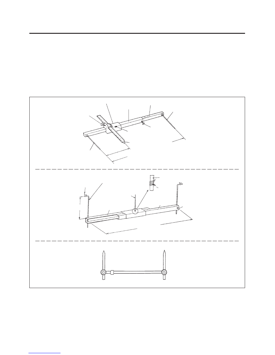
If there are any deviations, use a tram tracking gauge
and measure parts of the body.(Below Fig. 4-1)

If there is any twisting to the body, measure using a
frame centering gauge.(Below Fig. 4-2)

When measuring body dimensions, use a universal
tram gauge.(Below Fig. 4-3)

Fig. 3

Fig. 4-1

Fig. 4-2

Fig. 4-3

ADJUST SCREW A

POINTER  C HOLDER

REFERENCE SCALE

EXPANDING/CONTRACTING SCALE

POINTER B

POINTER  C

Adjust this to the diameter of the wheel disc.

Adjust this to the automobile.

ADJUST SCREW 

C

ADJUST SCREW 

B

POINTER  A

SET RING

POINTER  4

HEIGHT

FRAME

FRAME

A

CLIP

SET SCREW

4. MEASURING SYSTEMS

(WITHOUT SMALL DAMAGE)

Whenever possible, make judgements and conclu-
sions based on measurement. Measure the wheel
alignment(see pages 2-2, 2-3) so as to prevent any
future trouble like unsymmetrical wear of the tires or
catching of the steering wheel.

POINTER  B–  short pointer(height adjustment 15-290mm/0.59-11.42in.)

– long pointer(height adjustment 185-450mm/7.28-17.72in.)

Move within a range of
2 5 0 – 1 , 5 7 0 m m .

WELDING AND TOOLS  3–1

SECTION 3

WELDING  AND TOOLS

CONTENTS

SPOT WELDING .................................................................................................................................... 3-2

•  General description ...................................................................................................................... 3-2

•  Welding conditions ....................................................................................................................... 3-2

•  Welding strength test ................................................................................................................... 3-3

GAS WELDING ...................................................................................................................................... 3-4

CARBON DIOXIDE ARC WELDER ..................................................................................................... 3-5
(MIG ARC WELDING)

REPAIR TOOLS..................................................................................................................................... 3-6

3–2  WELDING AND TOOLS

Plate thickness

0.6

0.9

1.2

1.6

Minimum intervals

11

16

20

24

Fig. 1  Welders

Transformer

Spot welder

Timer

Intervals

Fig. 2

1. SPOT WELDING

1-1. GENERAL DESCRIPTION

Spot welding is also known as resistance spot welding
and it is the most suitable method of welding for auto-
mobiles. It has three main features: the welding can be
performed instantaneously, it exercises very little effect
on the mother material, and it reduces the generation
of distortion to the absolute minimum. However, please
remember to remove all paint and other impurities from
the surface of the material you intend to weld for reli-
able results.

1-2. WELDING CONDITIONS

When performing spot welding, make absolutely sure
that you conform to the conditions governed by the
current, conductivity time, welding pressure, holding
time, and shutdown time recommended for the spot
welder.

Please bear in mind the following points when welding:

Plate thickness and minimum welding pitch

NOTE: When the welding intervals are too small, this
leads to branching, making it impossible to maintain
the desired soldering state.

(Unit : mm)

WELDING AND TOOLS  3–3

1-3. WELDING STRENGTH TEST

Even if you perform the welding in accordance with the
conditions, the strength of the welded sections may fluc-
tuate widely with drops in the voltage and other factors.
The quality of the welding cannot be evaluated unless
the welded sections are destroyed.

Provide yourself with a steel plate of the same thick-
ness and conduct a destruction test.

If holes appear in the steel plates, this means that
the welding is standard strength.

Drive a wedge between two panels near the nug-
get. If the welded parts do not come apart and the
diameter of the nugget appears more than 3 mm,
the welding should be satisfactory.

Fig. 4

Stop inserting the wedge when
the full size of the nugget appears.

WEDGE

Plate thickness

0.6

0.9

1.2

1.6

Tip diamter

ø4.5

ø5.0

ø5.5

ø6.0

Fig. 3

Tip diameter

(Unit : mm)

Plate thickness and tip diameter

6 ~

9 m

m /

3 0 m m


Content   ..  4  5  6  7   ..