Daewoo Korando. Manual - part 32


  Index      Daewoo     Daewoo Korando - service repair manual


Search            


Content   ..  30  31  32  33   ..


Daewoo Korando. Manual - part 32


1B1-64  M162 ENGINE MECHANICAL

Adjustment  Procedure

1. Position the No.1 cylinder to BTDC 30° .

2. Remove the chain tensioner.

3. Remove the exhaust camshaft sprocket.

4. Align the intake and exhaust camshaft flange hole with the

cylinder head upper surface.

l

Intake Side : 3 o’clock direction

l

Exhaust Side : 9 o’clock direction

5. Secure the intake and exhaust camshaft.

6. Position the piston of No.1 cylinder at TDC (OT) by turning

the crankshaft.

7. Turn the camshaft adjuster of the intake camshaft to the

left as much as possible (cam adjuster ‘retarded’ position).

8. Install the chain to the intake camshaft sprocket.

Notice

Timing chain must be placed on the guide rail in gear case
cover.

Tools Required

104 589 01 01 00  Spanner

Inspection

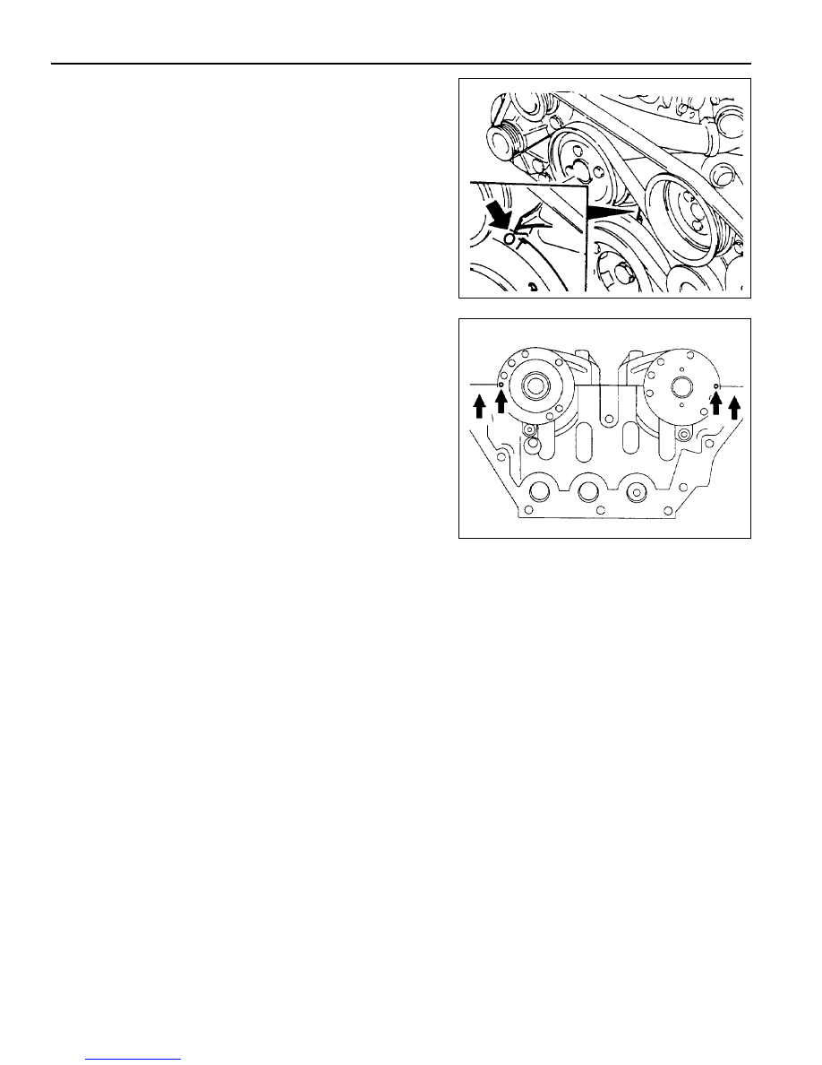
1. Position the No.1 cylinder piston to TDC (OT) by turning

the crankshaft.

Notice

When the OT mark on vibration damper is aligned with timing
gear case cover, the  intake and exhaust cam of cylinder
will make the slope to the center and will face up. In this
way, the adjustment hole of the intake and exhaust camshaft
will match in line with the cylinder head upper end, at 3
o’clock, and 9 o’clock direction each other.

2. Check the timing as below procedure;

-

Check if the camshaft adjustment hole is positioned to 3

o’clock direction at the intake side and to 9 o’clock
direction at the exhaust side, respectively and align with
the cylinder head mating surface.

-

At this condition, check if the OT mark on vibration

damper aligns with the marker on the timing gear case.

M162 ENGINE MECHANICAL  1B1-65

11. Check the camshaft timing.

The sprocket bolt is designed to be used only once, so
replace with new one.

10. Install the chain tensioner.

Installation Notice

Tightening Torque

1st step 18 - 22 Nm

2nd step 90° ± 5°

9. Install the chain to the exhaust camshaft sprocket and

install it to the camshaft.

Installation Notice (Sprocket Bolt)

Tightening Torque

Screw Plug

40 Nm

Tensioner Assembly 72 - 88 Nm

1B1-66  M162 ENGINE MECHANICAL

VALVE SPRING

Preceding Work : Removal of camshaft

Removal of spark plug

1 Valve Tappet Assembly
2 Valve Cotter
3 Upper Retainer
4 Valve Spring .......... Check, Replace if necessary
5 Valve Stem Seal
6 Lower Retainer

7 Connecting Hose
8 Thrust Piece
9 Slide

10 Adjust Bolt

11 Lever Pusher

12 Supporting Bar

M162 ENGINE MECHANICAL  1B1-67

Tools Required

111 589 01 59 00 Supporting Bar

111 589 18 61 00 Lever Pusher

111 589 25 63 00 Thrust Piece

116 589 06 63 00 Magnetic Finger

Removal & Installation Procedure

1. Place the supporting bar (12) and the slide (9) at the

camshaft bearing cap (Nos 1 & 7/8&14) and tighten them
with the bearing cap bolt.

Installation Notice

2. Turn the crankshaft to position the each cylinder piston at

TDC.

5. Install the engine lock to the ring gear to prevent the

crankshaft from rotating.

6. Blow up with compressed air.

Notice

l

Remove the valve spring only at TDC.

l

Always rotate the crankshaft by holding the chain to

prevent from timing chain damage and tangling, and for
smooth rotation.

3. Remove the valve tappet (1) using the magnetic finger.

4. Install the leakage tester connecting hose to the spark plug

hole.

Supporting  Bar  111  589  01  59  00

Tightening  Torque

22.5 - 27.5 Nm

Mark on The Vibration Damper

OT

120°

240

Cylinder

1, 6

2, 5

3, 4


Content   ..  30  31  32  33   ..