DAF CF65, CF75, CF85 Series . Manual - part 997


  Index      DAF     DAF CF65, CF75, CF85 Series - service repair manual


Search            


Content   ..  995  996  997  998   ..


DAF CF65, CF75, CF85 Series . Manual - part 997


©

 200423

2-5

Inspection and adjustment

STEERED TRAILING SWIVEL AXLE

ΧΦ65/75/85 series

7

7

2.2 INSPECTION AND ADJUSTMENT, CASTER

Inspection of caster
1.

Place the vehicle on a level and horizontal 

surface.

2.

Put the trailing axle in the "straight ahead" 

position.

3.

Use high-quality wheel alignment equipment 

for the inspection. The equipment must be 

calibrated regularly and preferably be of the 

type that can be calibrated before every use.

4.

Follow the instructions for the wheel 

alignment equipment carefully.

5.

Compare the reading with the specified 

value. See 'Technical data'.

6.

Carry out the caster measurement on the 

other axle side too.

If different readings are obtained, the axle 

suspension should also be inspected for 

deviations.

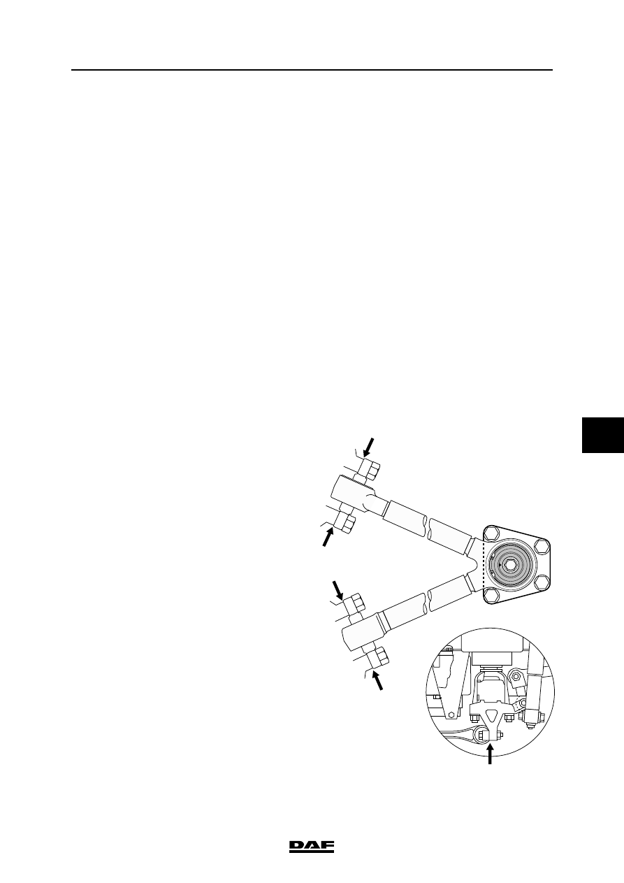
Adjusting the caster
1.

Adjust the caster by fitting hardened steel 

washers between attachment of the torque 

rods or the triangular link 

(DAF no. 0202838). The washers are 3 mm 

thick. Grind the washers if necessary. The 

application of more than one washer per bolt 

is not acceptable.

2.

Repeat the measurement once the steel 

washers have been fitted.

S7 00 728

STEERED TRAILING SWIVEL AXLE

2-6

©

 200423

Inspection and adjustment

7

ΧΦ65/75/85 series

7

2.3 INSPECTION OF CAMBER ANGLE AND KING PIN INCLINATION

Note:

In the following measurement, only the camber 

angle is measured. If the camber angle is correct, 

the king pin inclination must also be correct.

General

-

The vehicle should be on a flat and horizontal 

surface, with the steering gear in the "straight 

ahead" position.

-

The tyre pressure should be correct.

-

The camber angle can be measured using 

an angle measuring device or wheel 

alignment equipment.

-

The measurement should be carried out on 

both wheels.

Inspection of camber angle using angle 
measuring device
1.

Thoroughly clean the side of the wheel rim. 

Position the angle measuring device against 

the wheel rim. Keep the angle measuring 

device in the vertical position.

2.

Read off the angle shown. For the permitted 

angle, see 'Technical data'.

Inspection of camber angle using wheel 
alignment equipment
1.

Use high-quality wheel alignment equipment 

for the inspection. The equipment must be 

calibrated regularly and preferably be of the 

type that can be calibrated before every use.

2.

Follow the instructions for the wheel 

alignment equipment carefully.

For the permitted angle, see 'Technical data'.

The following points may cause the reading to 

deviate:

-

excessive swivel axle bearing play

-

bent front axle. In this case, the king pin 

inclination will also deviate from the values 

specified.

S7 00 566

©

 200423

2-7

Inspection and adjustment

STEERED TRAILING SWIVEL AXLE

ΧΦ65/75/85 series

7

7

2.4 INSPECTION AND ADJUSTMENT, TOE

Inspection of toe
1.

Use high-quality wheel alignment equipment 

for the inspection. The equipment must be 

calibrated regularly and preferably be of the 

type that can be calibrated before every use.

Follow the instructions for the wheel 

alignment equipment carefully.

2.

Ensure that the steering gear is free of 

tension. To that end, drive the vehicle, if 

possible, directly to the place of 

measurement. If this is not possible, drive 

forwards and backwards at the place of 

measurement with the steering gear in the 

"straight ahead" position. Do not brake 

excessively because of weight transmission 

to front axle.

3.

Measure the axle load of the axle being 

inspected.

4.

Measure the toe of the axle.

5.

Using the graph for the axle concerned, 

inspect whether the toe is correct or must be 

corrected (see 'Technical data').

There are two examples explaining how the 

graphs are to be read in 'Technical data'.

Note:

If a large deviation is measured, the cause should 

be traced. The deviation could, for example, have 

been caused by a collision, during which 

components were bent. If so, the remaining 

steering gear components should be inspected 

carefully.

Example 1
Look at the graph for the 152N axle, disc brake 

version, used as a leading rear axle or first front 

axle in a vehicle with two steered front axles.

The measured axle load is 4,000 kg and the 

measured toe is 2 mm/m (toe-in).

The intersection of the lines (A) occurs in the 

shaded area. This shows you that the toe is within 

the permitted tolerance.

The toe does not have to be corrected.

1

2

3

4

5

6

7

8

0

-1

0,5

-0,5

-1,5

1,5

2,5

3,5

4,5

5,5

-2

2

3

4

5

6

1

mm/m

152 N

x 1000 KG

A

S700910

STEERED TRAILING SWIVEL AXLE

2-8

©

 200423

Inspection and adjustment

7

ΧΦ65/75/85 series

7

Example 2
Look at the graph for the 152N axle, disc brake 

version, used as a single front axle or second 

front axle in a vehicle with two steered front axles.

The measured axle load is 5,000 kg and the 

measured toe is 1-mm/m (toe-out).

The intersection of the lines (B) occurs outside 

the shaded area. This shows you that the toe is 

outside the permitted tolerance. If the amount 

measured lies outside the shaded area, the toe 

must be adjusted to the amount indicated by the 

intersecting line (C).

Adjusting the track
1.

Slacken the bolts of the clamping brackets 

until the track rod can be rotated.

2.

Set the correct length by lengthening or 

shortening the track rod.

3.

Make sure that the threaded ends of the ball 

end are not screwed too far from the track 

rod. The clamping bracket should always 

fully engage the screw thread of the ball end 

(see drawing).

4.

Thoroughly clean and check the clamping 

bracket bolts. A corroded or damaged bolt 

must be replaced. Replace the self-locking 

nut.

5.

Tighten the locking bolts of the clamping 

brackets to the specified tightening torque. 

See 'Technical data'.

6.

After this, check the toe once again.

7.

Make sure that the clamping brackets do not 

come into contact with the axle housing at 

maximum wheel deflection. Turn the 

clamping brackets if necessary.

7

8

0

-1

0,5

-0,5

-1,5

1,5

2,5

3,5

4,5

5,5

-2

2

3

4

5

6

1

mm/m

152 N

x 1000 KG

5

B

1

2

3

4

6

C

S700911

S7 00 539


Content   ..  995  996  997  998   ..