DAF CF65, CF75, CF85 Series . Manual - part 928


  Index      DAF     DAF CF65, CF75, CF85 Series - service repair manual


Search            


Content   ..  926  927  928  929   ..


DAF CF65, CF75, CF85 Series . Manual - part 928


©

 200423

3-61

Removal and installation

BRAKE SYSTEM AND COMPONENTS

ΧΦ65/75/85 series

6

5

3.

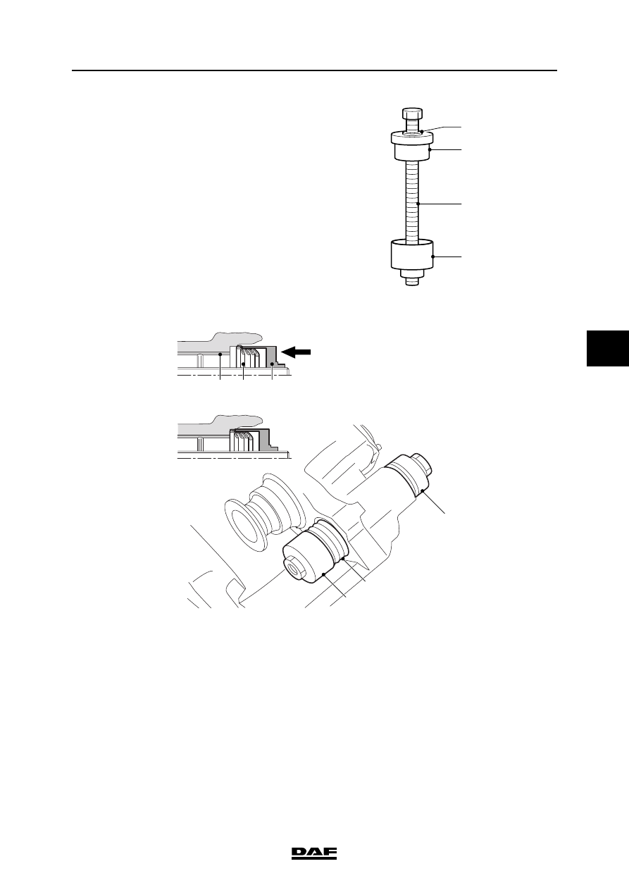
Assemble a press from the special tool set 
(DAF no. 1329495). To do this, use T7, T10, 
T8 and a washer.

4.

Place a new bellows (3) in the sleeve (5) 
of the assembled press.

5.

Place the press and bellows in the bore 
of the brake calliper. Hand-tighten the 
press (6).

6.

Tighten the press (6) to the specified torque. 
See "Technical data". Remove the press.

1

T8

T10

T7

R600761

5

3

4

5

3

6

R600724

BRAKE SYSTEM AND COMPONENTS

3-62

©

 200423

Removal and installation

5

ΧΦ65/75/85 series

6

7.

Check the bellows fastening by pulling it 
outwards by hand. Damage is not permitted.

8.

Apply lubricating grease to the bronze 
bearing bush and guide bush. See 
"Technical data".

9.

Install the guide bush (2).

10. Install the washer (1).

11. Check that the guide bush moves freely in 

the brake calliper.

12. Fit the brake calliper.

R600725

2

3

1

R600723

©

 200423

4-1

Disassembly and assembly

BRAKE SYSTEM AND COMPONENTS

ΧΦ65/75/85 series

6

5

4. DISASSEMBLY AND ASSEMBLY

4.1 DISASSEMBLY AND ASSEMBLY, BRAKE CHAMBER

Removal, diaphragm
1.

Turn the brakes back until the spring in the 
brake chamber is under tension.

2.

Mark the position of the brake chamber 
halves in relation to one another.

3.

Remove the clamping strap from the brake 
chamber.

4.

Remove the rear half of the brake chamber 
and the diaphragm.

Installation, diaphragm
1.

Fit the new diaphragm and brake chamber 
half. (Pay attention to the markings or the 
small drainage hole.)

2.

Fit the clamping strap.

3.

Adjust the brakes. See "Inspection and 
adjustment".

4.

Check the complete brake chamber for air 
leaks.

Disassembling the brake chamber
1.

Remove the yoke and the lock nut from the 
push rod.

2.

Slide a sealing ring and a piece of pipe over 
the push rod.

3.

Screw the lock nut onto the push rod until the 
spring in the brake chamber is slightly 
tensed.

4.

Mark the position of the brake chamber 
halves in relation to one another.

5.

Loosen the clamping strap and remove the 
brake chamber half, the push rod and the 
diaphragm.

Assembly, brake chamber
1.

Thoroughly clean all parts.

2.

Check all parts for damage and replace them 
if necessary.

3.

Replace the diaphragm in any case. Fit in the 
reverse order to removal.

BRAKE SYSTEM AND COMPONENTS

4-2

©

 200423

Disassembly and assembly

5

ΧΦ65/75/85 series

6

4.2 DISASSEMBLY AND ASSEMBLY, WABCO SPRING BRAKE CYLINDER

Disassembling the brake chamber
1.

Clean the spring brake cylinder.

2.

Remove the flexible bleed pipe with the 
internal sinter filter.

3.

Place a wrench on the yoke rod at the 
assembly surface of the brake chamber.

4.

Apply pressure to connection point (12) 
(min. 6.0 bar).

5.

Remove the clamping strap.

6.

Remove the front cover from the brake 
chamber.

7.

Remove the diaphragm.

8.

Remove the front cover from the yoke.

R600197

R600194


Content   ..  926  927  928  929   ..