DAF CF65, CF75, CF85 Series . Manual - part 914


  Index      DAF     DAF CF65, CF75, CF85 Series - service repair manual


Search            


Content   ..  912  913  914  915   ..


DAF CF65, CF75, CF85 Series . Manual - part 914


©

 200423

3-5

Removal and installation

BRAKE SYSTEM AND COMPONENTS

ΧΦ65/75/85 series

6

5

3.3 REMOVAL AND INSTALLATION OF PIPE ON PIPE CONNECTOR

When disconnecting pipes and/or 
quick-release couplings, ensure that 
the relevant connection has first 
been made pressureless.

Removal of pipe on pipe connector
1.

Remove the plug from the socket.

2.

Cut the pipe at right angles just in front of the 
pipe connector.

Note:
When removing the remainder of the pipe, 
do not use any sharp objects. This is to avoid 
damaging the pipe connector. Damage to 
the pipe connector could result in leakage.
Remove the remainder of the pipe using heat 
or the "cutting point" of a soldering iron.

Installation of pipe on pipe connector
1.

Check that there are no burrs in the pipe.

2.

Check the pipe connector for damage. 
If the pipe connector is damaged, the pipe 
connector and socket must be replaced.

3.

Check that the pipe connector is clean and 
grease-free.

4.

Fit the plastic cap onto the plug to prevent it 
from being damaged during installation.
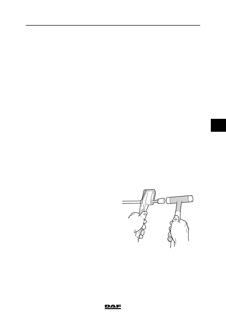
5.

Using the special tool (DAF no. 0694829) 
and a plastic hammer, attach the pipe to the 
pipe connector.

}

W602009

BRAKE SYSTEM AND COMPONENTS

3-6

©

 200423

Removal and installation

5

ΧΦ65/75/85 series

6

3.4 REMOVAL AND INSTALLATION, BRAKE CYLINDER

Removing disc brake cylinder
1.

Remove the compressed air connection to 
the brake cylinder.

2.

Take the attachment nuts off the brake 
cylinder and remove it.

Fitting disc brake cylinder
1.

Fit the brake cylinder onto the support and 
tighten the attachment nuts to the specified 
torque. See "Technical data".

2.

Connect the air pipe.

Removing drum brake cylinder
1.

Turn the brakes back until there is no more 
tension on the yoke pin.

2.

Remove the split pin and the yoke pin.

3.

Remove the compressed air connection to 
the brake cylinder.

4.

Take the attachment nuts off the brake 
cylinder and remove it.

Fitting drum brake cylinder
1.

Fit the brake cylinder onto the support and 
tighten the attachment nuts to the specified 
torque. See "Technical data".

2.

Insert the yoke pin and split pin.

3.

Connect the air pipe.

4.

Adjust the brakes. See "Inspection and 
adjustment".

©

 200423

3-7

Removal and installation

BRAKE SYSTEM AND COMPONENTS

ΧΦ65/75/85 series

6

5

3.5 REMOVAL AND INSTALLATION, SPRING BRAKE CYLINDER

Removal, spring brake cylinder on drum brake
1.

Place chocks in front of and behind the 
wheels and ensure that there is sufficient 
system pressure (> 7.5 bar).

2.

Place the parking brake valve in the "Driving" 
position. Unscrew the release bolt in the 
spring brake cylinder with a 24-mm spanner 
as far as possible (anti-clockwise).

3.

Place the parking brake valve in the 
"Parking" position and disconnect the two air 
pipes from the spring brake cylinder.

4.

Remove the yoke pin from the yoke and the 
brake lever.

5.

Remove the attachment nuts and take the 
spring brake cylinder from the support.

Installation, spring brake cylinder on drum 
brake
1.

Fit the spring brake cylinder onto the support 
and tighten it to the specified torque. See 
"Technical data".

2.

Pass the yoke pin through the yoke and the 
brake lever. The bracket should be flat 
(tolerance < 0.4 mm).

3.

Connect the air pipes:
connection point (11); service brake,
connection point (12); parking brake,

4.

Pressurise the air reservoirs and put the 
parking brake valve in the "Driving" position. 
Turn the release bolt all the way in and 
tighten it to the specified torque. See 
"Technical data".

5.

Check the connections for leakage.

Removal, spring brake cylinder on disc brakes

Note:
Prevent dirt from entering the disc brake 
construction and cover the opening.

1.

Place chocks in front of and behind the 
wheels and ensure that there is sufficient 
system pressure (> 7.5 bar).

2.

Put the parking brake valve in the "Driving" 
position (provide sufficient system pressure: 
+ 6 bar). Unscrew the release bolt in the 
spring brake cylinder with a 24-mm spanner 
as far as possible (anti-clockwise).

BRAKE SYSTEM AND COMPONENTS

3-8

©

 200423

Removal and installation

5

ΧΦ65/75/85 series

6

3.

Place the parking brake valve in the 
"Parking" position and disconnect the two air 
pipes from the spring brake cylinder.

4.

Remove the attachment nuts and take the 
spring brake cylinder from the support.

Installation, spring brake cylinder on disc 
brakes
1.

Fit the spring brake cylinder onto the support 
and tighten the attachment nuts to the 
specified torque. See "Technical data".

2.

Connect the air pipes:

3.

Put the parking brake valve in the "Driving" 
position (provide sufficient system pressure: 
approx. 6 bar). Turn the release bolt all the 
way in and tighten it to the specified torque. 
See "Technical data".

4.

Check the connections for leakage.


Content   ..  912  913  914  915   ..