DAF CF65, CF75, CF85 Series . Manual - part 560
 

  Index      DAF     DAF CF65, CF75, CF85 Series - service repair manual


Search            


Content   ..  558  559  560  561   ..


DAF CF65, CF75, CF85 Series . Manual - part 560


10

13

1358030/26

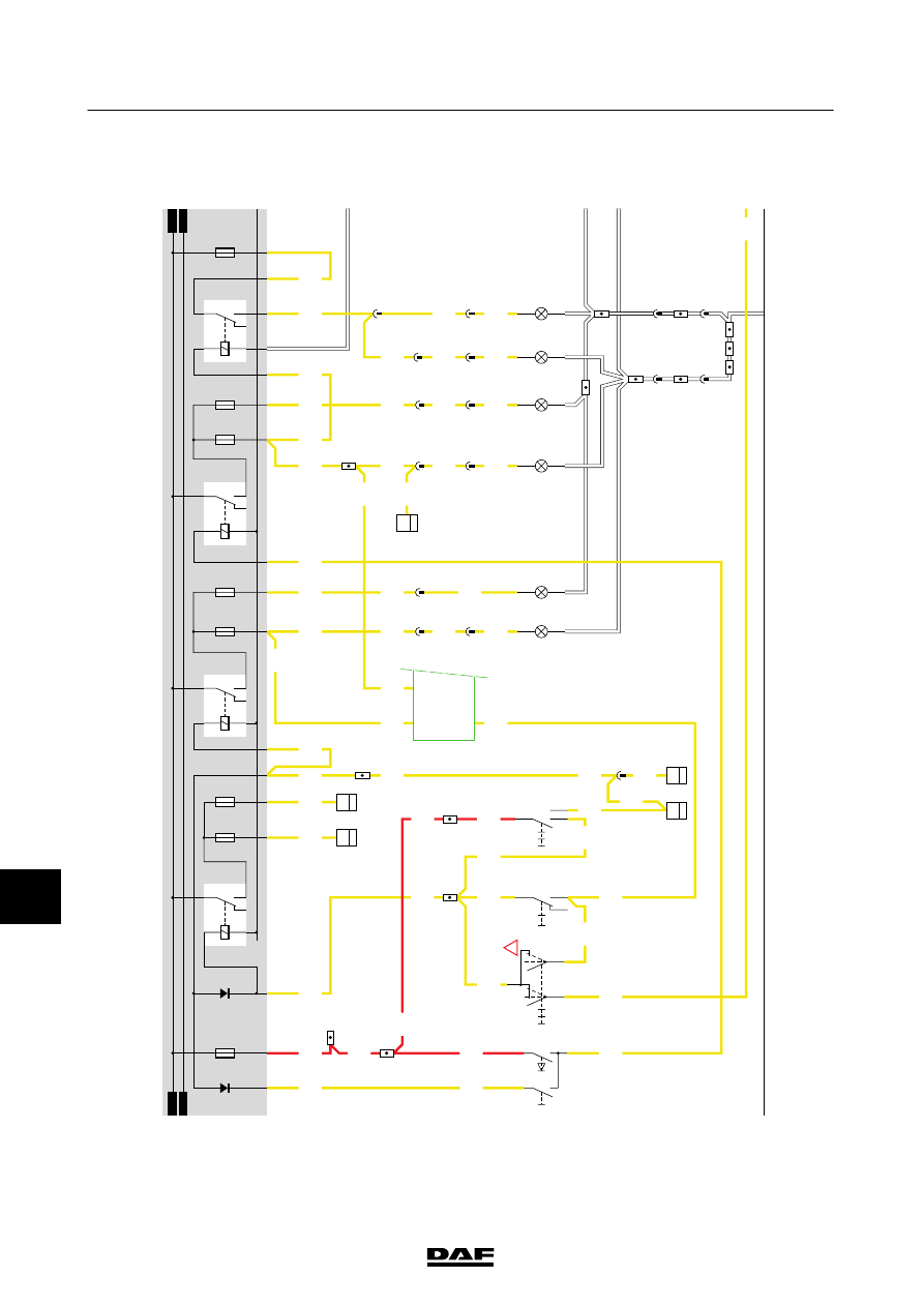
EL001317

1

23456789

1

0

1

1

1

2

1

3

1

4

1

5

1

6

1

7

1

8

1

9

2

0

2

1

2

2

2

3

2

4

2

5

2

6

2

7

2

8

2

9

3

0

3

1

3

2

3

3

3

4

3

5

3

6

3

7

3

8

3

9

4

0

4

1

4

2

4

3

4

4

4

5

4

6

4

7

4

8

4

9

5

0

5

1

5

2

5

3

1101

1101

1101

1101

1101

2154

2154

2100

2100

2100

2100

2100

2110

2110

2110

2114

2122

2122

2122

2114

2114

2110

2110

2150

2110

2110

2150

2120

2140

2114

2114

2113

2114

2113

2100

2150

1101

2102

2103

2120

2123

2113

2123

2123

2122

2122

2122

2132

2131

2122

2140

2122

2122

2132

2132

2132

2132

2132

2133

14/403

28/401

4

559

4

572

5

572

5

559

3

559

6

284

5

284

B129

1

35

17/403

C622

0II

I

2

14

22/401

24/401

C000

1

2

C002

1

2

7/401

16/403

6

C727

3

2

0

l

ll

C773

5

71

0I

C010

1

9

C764

5

35

33/400

D929

1010

1000

1010

1000

E084

10A

D610

D609

30

86

85

87A

87

G001

2112

2110

E004

10A

E005

10A

2110

M

M

30

86

85

87A

87

G000

2101

2100

E000

10A

C011

1

9

28/400

E001

10A

30

86

85

87A

87

G002

2121

2120

E006

10A

E007

10A

5/402

6

288

C813

6

33

C003

1

2

C001

1

2

28/402

C832

C5/

594

C6/

594

D900

D35/

595

A14/566

A8/566

A9/566

!

30

86

85

87A

87

G003

2131

2122

22/402

4/402

30/402

9/403

21/402

17/402

E008

15A

7

288

6

572

7

284

18

559

12

284

6

559

C006

1

2

C007

1

2

21

572

12

288

200404

2-80

5

ELECTRICAL SYSTEM

Electrical system

CF65/75/85 series ≥0E621376

10

13

1358030/26

EL001318

54

55

56

57

58

59

60

61

62

63

64

65

66

67

68

69

70

71

72

73

74

75

76

77

78

79

80

81

82

83

84

85

86

87

88

89

90

91

92

93

94

95

96

97

98

99

100

101

102

103

104

105

106

2140

2142

2142

2168

2152

2152

2142

2142

2142

2142

2142

2142

2152

2152

2152

2152

2152

2152

2152

2152

2152

2152

2142

2168

2152

2140

5

915

19/401

5/401

8

288

7

572

8

284

7

559

C008

1

2

C009

1

2

7

873

C024

1

2

C025

1

2

C024

1

2

C025

1

2

3/401

2/401

6/401

24/400

D

873

8

877

D929

1010

1000

1010

1000

M

30

86

85

87A

87

G004

2141

2140

E009

10A

30

86

85

87A

87

G005

2151

2168

E010

10A

M

A001

71

!

5

877

!

!

!

!

!

D34/

595

C40/

594

D900

8

916

!

!

200404

2-81

Electrical system

5

ELECTRICAL SYSTEM

CF65/75/85 series ≥0E621376

10

14

SWEDISH

L

IGHTING

Conditions:

E

ngine

running,

switch

C622

has

N

OT

been

operated.

If

the

engine

is

running

and

switch

C622

has

NOT

been

operated,

relay

G

301

is

activated

by

a

voltage

from

connection

point

C42

of

D900

(VIC).

A

voltage

is

then

applied

to

connection

point

85

of

relay

G

001

(dipped

beam

relay)

through

fuse

E084,

wire

1101,

contacts

5

-

3

of

relay

G301,

wire

2100,

contacts

3

-

4

of

relay

G302

and

wire

21

10.

The

same

voltage

is

also

applied

to

connection

point

85

of

relay

G

000

(rear

light/width

marker

light

relay)

through

diode

D609.

Both

relays

are

energised.

When

relay

G

000

is

energised

(connection

between

contacts

30

and

87),

a

voltage

is

applied

to

the

left

and

right

width

m

arker

lights

in

the

headlights

through

contacts

30

-

87

of

relay

G

000,

PCB

track

2101,

fuses

E

000

and

E001

and

wire

2102.

When

relay

G

001

is

energised

(connection

between

contacts

30

and

87),

a

voltage

is

applied

through

contacts

30

-

87

of

relay

G001,

PCB

track

21

12,

fuse

E004

and

fuse

E005.

The

voltage

through

wire

21

14

is

applied

to

connection

point

1

of

C

000

(left

dipped

beam)

through

fuse

E004.

The

voltage

through

wire

21

13

is

applied

to

connection

point

1

of

C

001

(right

dipped

beam)

through

fuse

E005.

A

voltage

is

also

applied

to

the

VIC

via

wire

21

14,

pin

C

5.

The

V

IC

controls

the

D

IP

,w

hich

ensures

that

the

“dipped

beam”

w

arning

indicator

illuminates

on

the

instrument

panel.

Conditions:

E

ngine

running,

switch

C622

in

position:

marker

lights

(position

1).

When

the

engine

is

running

and

switch

C622

is

in

the

‘marker

lights’

position

(connection

between

2

and

1),

the

following

occurs:

Relay

G

301

is

energised,

making

a

connection

between

contacts

5

and

3.

The

voltage

is

now

applied

to

w

ire

2100

and

to

connection

point

85

of

relay

G

000

through

fuse

E084,

wire

1101,

contacts

5-3

of

relay

G301

.W

hen

relay

G

000

is

energised

a

voltage

is

applied

through

relay

contacts

30

-

87

of

relay

G000,

wire

2101,

fuses

E

000

and

E001

and

wire

2102

and

wire

2103

respectively

.T

he

corner

marker

lights,

marker

lights

and

rear

lights

(on

both

the

driver

’s

and

co-driver

’s

side)

now

come

on.

There

is

also

a

voltage

on

connection

point

1

of

relay

G

302

through

fuse

E084,

wire

1101,

contacts

2

-

1

of

switch

C

622,

wire

2105.

Relay

G

302

is

energised,

breaking

contacts

3-4

.

There

is

no

longer

a

voltage

on

wire

21

10

and,

as

a

result,

relay

G

001

is

no

longer

energised.

Contacts

30

-

87

are

now

broken

and,

as

a

result,

the

driver

’s

and

co-driver

’s

side

headlights

go

out.

Conditions:

E

ngine

not

running,

switch

C622

in

position:

dipped

b

eam

(position

2).

When

the

engine

is

not

running

and

switch

C622

is

in

the

‘dipped

beam’

position

(position

2)

(connection

between

2

and

4),

the

following

ta

kes

place:

Relay

G

301

is

energised,

making

a

connection

between

contacts

5

and

3.

The

voltage

is

now

applied

to

w

ire

2100

and

to

connection

point

85

of

relay

G

000

through

fuse

E084,

wire

1101,

contacts

5

-

3

of

relay

G301

.W

hen

relay

G

000

is

energised

a

voltage

is

applied

through

relay

contacts

30

-

87

of

relay

G000,

wire

2101,

fuses

E

000

and

E001

and

wire

2102

and

wire

2103

respectively

.T

he

corner

marker

lights,

marker

lights

and

rear

lights

(on

both

the

driver

’s

and

co-driver

’s

side)

now

come

on.

Because

there

is

a

voltage

on

connection

point

85

of

relay

G001

through

contacts

2

-

4

of

switch

C

622,

wire

21

10,

this

relay

is

energised.

When

relay

G001

is

energised,

a

voltage

is

applied

to

both

the

left

and

right

dipped

beam

through

contacts

30

-

87,

wire

21

12,

fuses

E

004

and

E005

and

wires

21

13

and

21

14

respectively

.A

voltage

is

also

sent

to

the

V

IC

via

w

ire

21

14,

pin

C

5.

The

V

IC

controls

the

D

IP

,w

hich

ensures

that

the

“dipped

beam”

w

arning

indicator

illuminates

on

the

instrument

panel.

200404

2-82

5

ELECTRICAL SYSTEM

Electrical system

CF65/75/85 series ≥0E621376

10

VARIANTS

Location 5,

16,

19

Connector

529

fitted

on

Swedish

lighting

version.

200404

2-83

Electrical system

5

ELECTRICAL SYSTEM

CF65/75/85 series ≥0E621376


Content   ..  558  559  560  561   ..