DAF CF65, CF75, CF85 Series . Manual - part 515


  Index      DAF     DAF CF65, CF75, CF85 Series - service repair manual


Search            


Content   ..  513  514  515  516   ..


DAF CF65, CF75, CF85 Series . Manual - part 515


5

CF65/75/85 Series ≥0E621376

Connection of accessories

CONNECTION OF ACCESSORIES

1-19

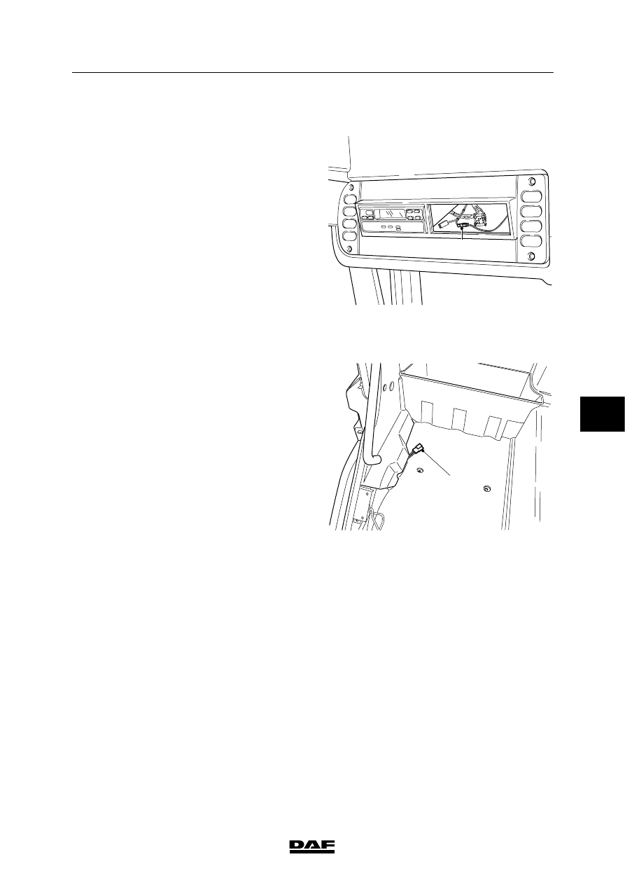
1.11 CONNECTOR FOR ALARM/IMMOBILISER LED IN ROOF CONSOLE

In the roof console there is a black 2-pin

connector (A). This is for connecting an alarm

LED.

This alarm LED is fitted as standard if the

vehicle does not have an alarm system. This

connector contains wires 1264 and 3482.

E501062

A

1.12 CONNECTOR FOR COOLER BOX

The wiring for the cooler box has been fitted as

standard ready for use behind the door pillar

trim (connector no. 618) on the co-driver’s side.

This connector contains the following wires:

1154 and M.

The cooler box (if present) is connected here to

the connector on the co-driver’s side.

The lighting for the tool compartment is

connected here to the connector on the driver’s

side.

ATTENTION: The power supply before contact

is fuse-protected via fuse E142

(25A). The power supply for the

superstructure functions bulkhead

lead-through connector (if

present), spotlights and rotating

beams is also via these fuses.

E501102

618

6

 200520

5

CONNECTION OF ACCESSORIES

Connection of accessories

CF65/75/85 Series ≥0E621376

1-20

1.13 CONNECTORS FOR CONNECTING THE RADIO

Radio connection

Behind the radio panel there is a connector

(connector no. 424) (to ISO standard) for the

radio connection; this connector is provided with

a 12 V/10 A (20 A) power supply before contact

(1108) and earth. The wiring to the door, A-pillar

and rear wall for the loudspeakers (connector

425) has also been fitted as standard ready for

use. If tweeters are fitted, a separating filter

should be fitted.

Connectors for connecting the radio.

E501041

424

425

GS

424

1

3

5

7

2

4

6

8

BN

425

1

3

5

7

2

4

6

8

424 Power supply to radio

425 Loudspeakers for radio

6

 200520

5

CF65/75/85 Series ≥0E621376

Connection of accessories

CONNECTION OF ACCESSORIES

1-21

DISPLAY LIGHTING DIMMING

VDO Dayton and Grundig radio

If the radio has display lighting (search lighting),

it can switch on at the same time as the vehicle

lights are switched on. The display lighting can

be dimmed by connecting relay G231 in

accordance with the diagram.

Relay G231 should be connected to search

lighting wire 2630.

+

+

+

+

+

+

+

+

+

+

4541

4543

B180 

B181 

B179 

4540

4542

B178 

4827

4828

B024 

4831

4832

B025 

B365

D895

12V

12V

12V

12V

24V

1108

480 301

030

A7

A6

A8 B8 B7 B6

B5

B2 B1 B4

B3

A4

1000
1010

B1

A4

B2

A3

A1

A2

1107 

1130

1240

E501969

G377 

1

2

1363

3

5

4

G377

385 

VDO Dayton radio station memory

Wire 1130 is switched by the ignition/starter

switch “accessories” position. Relay G377 then

switches and, as a result, the radio is connected

to the 12 V power supply through wire 1108.

Grundig radio station memory

Wire 1130 is switched by the ignition/starter

switch “accessories” position.

Relay G377 then switches and, as a result, the

radio is connected to the 12 V power supply

through wire 1108.

Wires 1108 and 1363 in connector no. 424 (the

“ISO connector”) must be reversed (see

illustration).

+

+

+

+

+

+

+

+

+

+

4541

4543

B180 

B181 

B179 

4540

4542

B178 

4827

4828

B024 

4831

4832

B025 

B365

D895

12V

12V

12V

12V

24V

1108

480 301

030

A4

A6

A8 B8 B7 B6

B5

B2 B1 B4

B3

A7

1000
1010

B1

A4

B2

A3

A1

A2

1107 

1130 

1240

E501970

G377 

1

2

1363

3

5

4

G377

385 

The wiring for the speakers in the rear wall of

the SL and SH cabs has been fitted in the

speaker positions ready for use.

The wiring for tweeters has been fitted ready for

use in the A-pillar under the dashboard.

6

 200520

5

CONNECTION OF ACCESSORIES

Connection of accessories

CF65/75/85 Series ≥0E621376

1-22

1.14 CONNECTOR FOR CONNECTING THE TELEPHONE

Telephone connection

There is space for a telephone connection on

the right side of the radio panel.

A white 3-pin connector (A076) is fitted behind

the radio panel as standard.

E501042

A076

Pin no.

Wire no.

Description

1

1108

Power supply before contact (12 V)

2

1353

Power supply before contact (12V/25mA)

3

M

Earth

6

 200520


Content   ..  513  514  515  516   ..