DAF CF65, CF75, CF85 Series . Manual - part 512
5
CF65/75/85 Series ≥0E621376
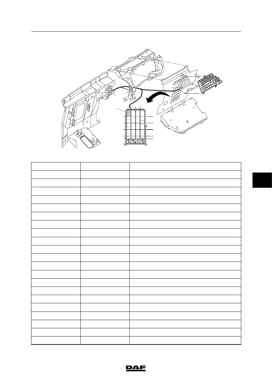
Connection of accessories
CONNECTION OF ACCESSORIES
1-7
A
B
C
D
656
654
655
580
2
3
4
5
7
8
9
1
2
3
4
5
6
7
8
9
10
E501029
Pin layout, wiring harness connector 656:
Pin no.
Wire no.
Description
1
M
Earth
2
M
Earth
3
4
3412
“Cab locking” signal
5
res 1
Panic switch signal
6
res 2
Reserve 2
7
res 3
Reserve 3
8
res 4
Reserve 4
9
res 5
Reserve 5
10
res 6
Reserve 6
11
res 7
Reserve 7
12
res 8
Reserve 8
13
res 9
Reserve 9
14
res 10
Reserve 10
15
res 11
Reserve 11
16
res 12
Reserve 12
17
18
19
3157
“Engine running” signal
20
1154
Power supply before contact
21
1258
Power supply after contact
6
200520