DAF CF65, CF75, CF85 Series . Manual - part 420


  Index      DAF     DAF CF65, CF75, CF85 Series - service repair manual


Search            


Content   ..  418  419  420  421   ..


DAF CF65, CF75, CF85 Series . Manual - part 420


©

 200416

4-3

Inspection and adjustment

CE ENGINE FUEL SYSTEM

ΧΦ65/75/85 series

4

2

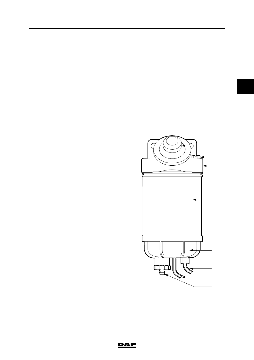
4.2 VENTING THE FUEL SYSTEM

When venting the fuel system, a 
quantity of fuel will escape. Collect 
the fuel and avoid the risk of fire.

Stop pumping as soon as a 
resistance is felt. If you continue 
pumping, the fuel system may 
become internally damaged.

Note:
When the primer pump is used, the fuel system 
will be automatically vented. Air will be fed back 
to the tank through the return line.

Racor fuel prefilter/water separator
1.

Open the vent plug (2) a couple of turns.

2.

Pump the primer pump (1) until fuel comes 
out of the vent plug (2).

3.

Close the vent plug (2).

4.

Use the primer pump until a clearly higher 
resistance is felt.

}

}

1

2

3

4

7

6

8

i400356

CE ENGINE FUEL SYSTEM

4-4

©

 200416

Inspection and adjustment

2

ΧΦ65/75/85 series

4

Fleetguard fuel prefilter/water separator
1.

Unscrew the button of the primer pump and 
pull it out.

2.

Use the primer pump until a clearly higher 
resistance is perceptible.

3.

Hand-tighten the button.

i4 00 712

©

 200416

4-5

Inspection and adjustment

CE ENGINE FUEL SYSTEM

ΧΦ65/75/85 series

4

2

4.3 CHECKING FUEL LIFT PUMP PRESSURES

When inspecting the fuel pressure, 
fuel will escape. Collect the fuel and 
avoid the risk of fire. 

Dirt in the fuel system can lead to 
significant damage to parts of the 
system. Prevent this by cleaning the 
parts before disassembly and then 
sealing all open connections.

Checking underpressure on suction side of 
fuel lift pump
1.

Disconnect the fuel pipe from the electronic 
unit cooling plate to the fuel lift pump on the 
suction side of the fuel lift pump; see 
"Removal and installation".

2.

Fit the adapter (1), special tool 
(DAF no. 1329476), between the pipe which 
has been removed and the fuel lift pump and 
couple a pressure gauge (2) to this adapter.

3.

Bleed the fuel system.

4.

Measure the underpressure when the engine 
is idling. Compare the readings with the 
specified values. See "Technical data".

5.

Remove the pressure gauge and the adapter 
and fit the fuel pipe.

6.

Bleed the fuel system, start the engine and 
check the fuel system visually for leaks if no 
further measurements are to be carried out.

Checking fuel pressure in fuel lift pump in 
front of fuel fine filter
1.

Disconnect the fuel pipe from the lift pump to 
the fuel fine filter on the delivery side of the 
lift pump; see "Removal and installation".

}

}

i400883

2

1

CE ENGINE FUEL SYSTEM

4-6

©

 200416

Inspection and adjustment

2

ΧΦ65/75/85 series

4

2.

Fit the adapter (1), special tool 
(DAF no. 1329476), between the pipe which 
has been removed and the fuel lift pump and 
couple a pressure gauge (2) to this adapter.

3.

Bleed the fuel system.

4.

Start the engine and measure the pressure 
when the engine is idling. Compare the 
readings with the specified values. See 
"Technical data".

5.

Remove the pressure gauge and the adapter 
and fit the fuel pipe.

6.

Bleed the fuel system, start the engine and 
check the fuel system visually for leaks if no 
further measurements are to be carried out.

Checking fuel pressure in fuel lift pump after 
fuel fine filter
1.

Disconnect the fuel pipe from the fuel fine 
filter to the high-pressure pump on the side of 
the high-pressure pump; see "Removal and 
installation".

2.

Fit the adapter (1), special tool 
(DAF no. 1329476), between the pipe which 
has been removed and the high-pressure 
pump and couple a pressure gauge (2) to 
this adapter.

3.

Bleed the fuel system.

4.

Disconnect the electrical connectors of the 
injectors from the valve sleeve.

5.

Start the engine and measure the pressure 
when the engine is idling. Compare the 
readings with the specified values. See 
"Technical data".

6.

Connect the electrical connectors of the 
injectors to the valve sleeve.

7.

Remove the pressure gauge and the adapter 
and reconnect the fuel pipe.

8.

Bleed the fuel system, start the engine and 
check the fuel system visually for leaks if no 
further measurements are to be carried out.

i400883

2

1

i400883

2

1


Content   ..  418  419  420  421   ..