DAF CF65, CF75, CF85 Series . Manual - part 382


  Index      DAF     DAF CF65, CF75, CF85 Series - service repair manual


Search            


Content   ..  380  381  382  383   ..


DAF CF65, CF75, CF85 Series . Manual - part 382


3

CF65/75/85 series

General

PTO

2-23

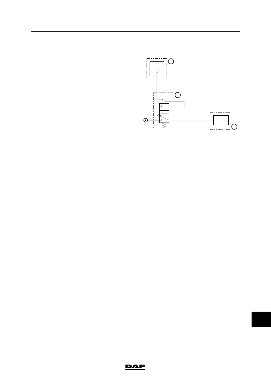
2.21 PNEUMATIC DIAGRAM, PTO CONTROL

Description
Depending on the version, the electropneumatic
valve (1) is controlled by a switch or a
combination of a switch and GV pressure sensor
located in the cab. By operating the PTO control
switch, voltage is applied to the VIC electronic
unit (3). This voltage can also come from the
engine speed control application connector.

Depending on the programmed switching
conditions, the VIC applies voltage to the
electropneumatic valve (1).

Upon activation of the electropneumatic valve
(1), there is system pressure on the
PTO connection, causing the PTO (2) to be
activated. These switching conditions may be
changed with DAVIE.

When the PTO (2) is switched on, the
PTO control switch is activated and the VIC
receives the feedback that the PTO is switched
on mechanically.

V300655

PTO

3

6

1

2

2

2

1

3

+

13

ᓻ 200337

3

PTO

General

CF65/75/85 series

2-24

13

ᓻ 200337

3

CF65/75/85 series

Inspection and adjustment

PTO

3-1

3. INSPECTION AND ADJUSTMENT

3.1 INSPECTION AND ADJUSTMENT, DAF ENGINE PTO PROP SHAFT AXIAL

PLAY

Inspection and adjustment, DAF engine PTO
prop shaft axial play
1.

Press the two outer bearing races into the
PTO housing.

2.

Fit the inner bearing (2) onto the
engine PTO driving tool (1) (special tool,
DAF No. 1329341).

V300633

1

2

3

4

5

6

7

3.

Fit the driving tool with the flat sides firmly
secured in a vice.

4.

Slide the PTO housing properly over the
driving tool.

V300634

5.

Fit the filler sleeve (3) and 2 shims (4)
properly onto the driving tool (1).

Take note of the reconditioned rim in the
filler sleeve (3).

Note:
Use the driving tool to determine the correct
assembly of the filler sleeve and shims.

V300635

1

4

3

13

ᓻ 200337

3

PTO

Inspection and adjustment

CF65/75/85 series

3-2

6.

Fit the inner bearing (5) and the knurled
sleeve (6) onto the driving tool (the knurled
sleeve is used to simulate the
PTO gearwheel).

7.

Fit the lock nut (7) and tighten to the
specified torque. See “Technical data”.

V300633

1

2

3

4

5

6

7

8.

Place the dial gauge holder onto the
PTO housing and allow the stylus of the dial
gauge to rest on the driving tool.

9.

Check the bearing play by moving the
PTO housing up and down relative to the
clamped driving tool in the axial direction.
See “Technical data”.

Note:
Select the proper shim if the axial play is
incorrect.

10. Disassemble the driving tool fully when the

correct shim thickness has been
established. See “Technical data”.

V300656

13

ᓻ 200337


Content   ..  380  381  382  383   ..