DAF CF65, CF75, CF85 Series . Manual - part 369


  Index      DAF     DAF CF65, CF75, CF85 Series - service repair manual


Search            


Content   ..  367  368  369  370   ..


DAF CF65, CF75, CF85 Series . Manual - part 369


3

CF65/75/85 series

Inspection and adjustment

ZF INTARDER

3-3

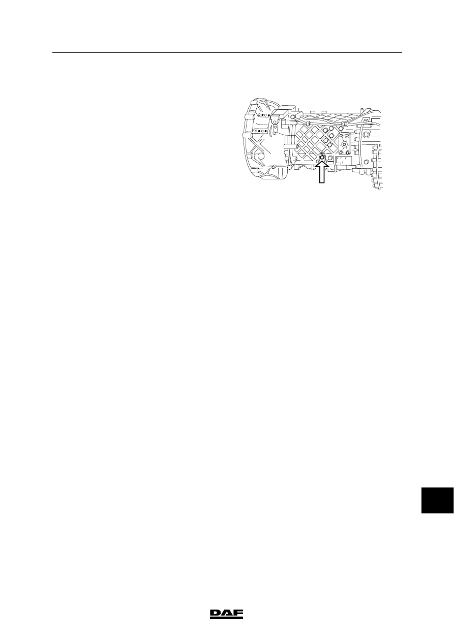
3.3 INSPECTION, GEARBOX/INTARDER OIL LEVEL

Inspection, gearbox/intarder oil level
1.

Slow the vehicle down without using the
intarder and place the vehicle on a level
surface.

2.

Wait for some minutes for the gearbox oil to
flow back.

3.

The oil level must reach the rim of the oil
level check opening (A).

M3051

A

12

ᓻ 200337

3

ZF INTARDER

Inspection and adjustment

CF65/75/85 series

3-4

12

ᓻ 200337

3

CF65/75/85 series

Removal and installation

ZF INTARDER

4-1

4. REMOVAL AND INSTALLATION

4.1 REMOVAL AND INSTALLATION, INTARDER ASSEMBLY

To prevent skin injury, avoid
unnecessary contact with the
drained oil.
In the course of the following
operations, oil will spill from the
gearbox and intarder. Collect this
oil.

Removing the intarder assembly
1.

Remove the prop shaft bolts and hang the
prop shaft to the side in the chassis.

2.

Drain the gearbox via drain plugs (1 and 2).

3.

Drain as much coolant and gearbox oil as
necessary and collect in clean containers.

4.

Disconnect the water hoses from both sides
of the heat exchanger.

5.

Remove the air pipe from the intarder
solenoid valve.

6.

Remove all electrical wiring from the
intarder.

7.

Remove the locking plate from the output
prop shaft flange, remove the disk with the
O-ring, and pull the drive flange from the
shaft using a tripod puller.

In the course of the following
operations, the intarder is
disconnected from the gearbox.
Take measures to prevent the
intarder from dropping.

8.

Remove the attachment bolts from the
intarder and remove the intarder.

9.

Remove the gasket and shims from the
adjustment stator/output shaft.

V300261

3

1

2

12

ᓻ 200337

3

ZF INTARDER

Removal and installation

CF65/75/85 series

4-2

Installing the intarder assembly
1.

Stick the correct shims onto the contact
surfaces using a little grease. See
“Inspection and adjustment”.

2.

Fix the gasket in the gearbox with as many
long studs as possible. The studs also
serve as guiding pins to facilitate mounting
of the intarder

3.

Carefully position the intarder on the
gearbox and tighten the attachment bolts to
the specified torque. See “Technical data”.

4.

Insert the prop shaft attachment bolts from
the correct side into the output prop shaft
flange (bolt end faces prop shaft).

5.

Install the output prop shaft flange without
heating it.

6.

Install the O-ring and the disk.

7.

Install the attachment bolts and tighten
them to the specified torque. See “Technical
data”.
Fit the lock plate using the special tool
(DAF No. 0694903).

8.

Connect the water hoses to the heat
exchanger.

9.

Connect the air pipe to the solenoid valve.

10. Make all electrical connections to the

intarder.

11. Install the prop shaft and tighten the prop

shaft attachment bolts to the specified
torque. See “Technical data”.

12. Fill the coolant system and fill the intarder

and gearbox with oil.

13. Check the operation of the intarder and

check for leaks.

14. Check the oil level in the gearbox. See

“Inspection and adjustment”.

V300078

12

ᓻ 200337


Content   ..  367  368  369  370   ..