DAF CF65, CF75, CF85 Series . Manual - part 327


  Index      DAF     DAF CF65, CF75, CF85 Series - service repair manual


Search            


Content   ..  325  326  327  328   ..


DAF CF65, CF75, CF85 Series . Manual - part 327


3

CF65/75/85 series

Removal and installation, gearbox

ZF 8/9/16S-109 GEARBOX

4-1

4. REMOVAL AND INSTALLATION, GEARBOX

4.1 REMOVAL AND INSTALLATION , ENTIRE GEARBOX

Removing the entire gearbox
1.

Make sure there are no loose items in the
cab. Tilt the cab.

2.

Disconnect the negative terminal of the
battery.

3.

Disconnect the prop shaft and flange from
the gearbox.

4.

Remove the clutch servo without
disconnecting the pipes.

5.

Disconnect the tachometer connection from
the gearbox.

6.

Disconnect the gearbox wiring harness
connector.

7.

Remove the various air pipes. Pipes that
are not recognisable must be marked.
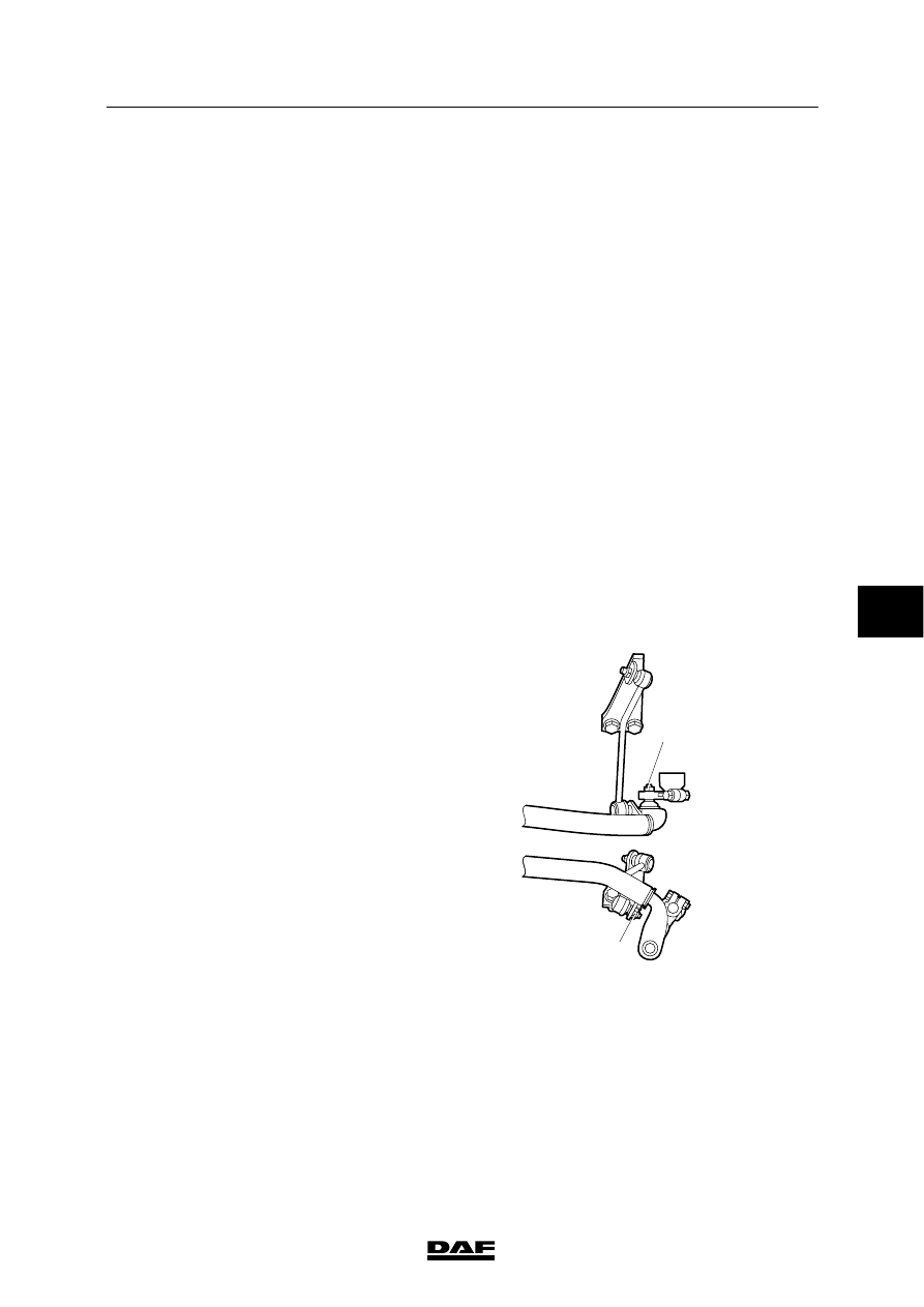
8.

Disconnect the selector rod from the
operating lever and the torque rod bracket
from the gearbox. Hang the gearbox control
on the chassis.

9.

Remove the exhaust pipe between the
engine brake and silencer (depending on
the vehicle type).

10. Place a jack under the gearbox and remove

the bolts around the clutch housing.

11. Use the jack to pull the gearbox from the

engine and remove the gearbox.

V300407

4

5

6

ᓻ 0111

3

ZF 8/9/16S-109 GEARBOX

Removal and installation, gearbox

CF65/75/85 series

4-2

Installing the entire gearbox
1.

Before positioning the gearbox, one gear
should be engaged in order to allow the
input shaft to slide into the clutch plate
during installation. Also grease the input
shaft sparingly with the specified grease.
See “Technical data”.

2.

Fit the exhaust pipe between the engine
brake and the silencer (depending on the
vehicle type).

3.

Fit the selector rod and torque rod.

4.

Fit the air pipes.

5.

Fit the gearbox connectors and the
tachometer connection.

6.

Fit the clutch servo.

7.

Fit the prop shaft flange to the gearbox.
Tighten the attachment bolts to the
specified torque. See “Technical data”.

8.

Connect the negative terminal of the
battery.

9.

Check the oil level after installing the
gearbox.

10. Inspect the shift control. See “Inspection

and adjustment”.

11. If a gearbox of a different type is mounted,

or a gearbox with a different reduction, this
should be reported. If the correct data are
present, they can be input into the VIC
using DAVIE XD.

ᓻ 0111

6

3

CF65/75/85 series

Removal and installation, gearbox

ZF 8/9/16S-109 GEARBOX

4-3

4.2 REMOVAL AND INSTALLATION, DRIVE FLANGE

Removing the drive flange
1.

Detach the prop shaft from the flange and
secure it.

2.

Hold the drive flange in place with special
tool (DAF No. 0484977).

3.

Remove the bolts and lock plate from the
drive flange.

4.

Remove the O-ring.
Recommendation: measure and note the
distance from flange to shaft. The same
distance must be observed when the flange
is reinstalled. Then the flange will be fitted
far enough on the shaft.

5.

Pull the flange from the shaft with a
commercially available puller.

Installing the drive flange
1.

Lightly oil the oil seal in the bearing cover.

2.

Heat the drive flange to 70

_C. Slide the

flange as far as possible onto the output
shaft. With the locking plate and two
standard bolts, pull the flange further onto
the shaft. Check the position of the flange,
comparing it with the above-mentioned
measurement in point 5. Remove the
locking plate and bolts.

3.

Press the new O-ring into the slot between
the shaft and flange.

4.

Hold the drive flange in place with special
tool (DAF No. 0484977).

Note:
For the new gearboxes the attachment bolts
are no longer locked with a locking plate,
but with self-locking screw thread in the
output shaft.
When the drive flange is removed during
overhaul, the bolts must always be
locked afterwards with a locking plate.

1

V300357

ᓻ 0111

6

3

ZF 8/9/16S-109 GEARBOX

Removal and installation, gearbox

CF65/75/85 series

4-4

5.

Apply a suitable locking compound between
the rear of the washer (1) and the drive
flange. See “Technical data”.

6.

Install the locking plate with the bolts and
tighten them to the specified torque. See
“Technical data”.

Note:
Bolts that will be re-used must be cleaned
and lightly oiled.

7.

Fit a new locking plate (DAF No. 0699725)
with stamp over the bolt heads.

1

V300356

6

ᓻ 0111


Content   ..  325  326  327  328   ..