DAF CF65, CF75, CF85 Series . Manual - part 266


  Index      DAF     DAF CF65, CF75, CF85 Series - service repair manual


Search            


Content   ..  264  265  266  267   ..


DAF CF65, CF75, CF85 Series . Manual - part 266


©

 200324

5-5

Removal and installation

XE ENGINE COOLING SYSTEM

CF65/75/85 series

2

9

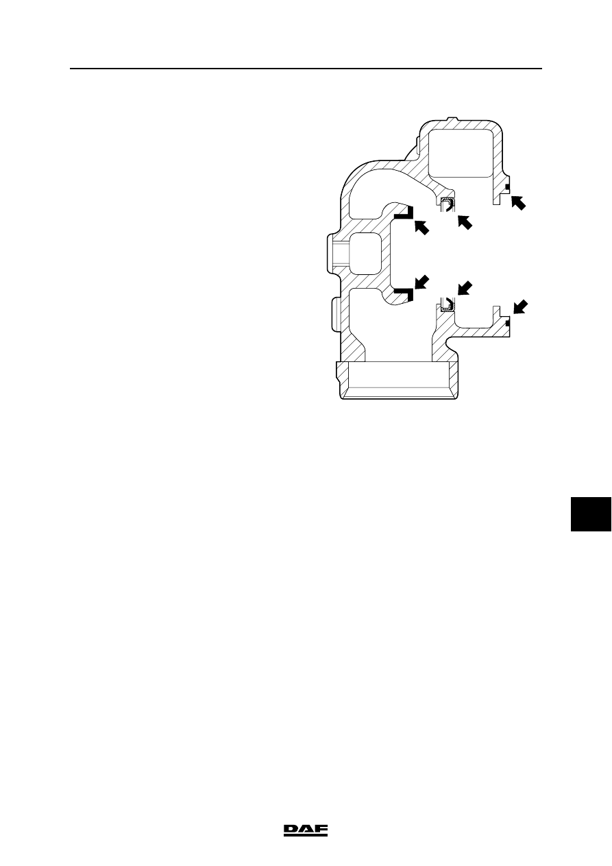
Installing the thermostat seat
1.

Apply locking compound to the thermostat 

seat (C) and fit it in the thermostat housing 

using the special tool (DAF no. 1310456). 

See "Technical data".

Installing the thermostat oil seal
1.

Fit the thermostat seal (B) in the thermostat 

housing using the special tool 

(DAF no. 1310456).

Installing the thermostat
1.

Connect the coolant pipe.

2.

Fit the O-ring (A) in the thermostat housing. 

Fit new O-rings to the connection piece from 

the thermostat housing to the coolant pump, 

and fit the connection piece in the thermostat 

housing.

3.

Fit the thermostat housing attachment bolts. 

Tighten the attachment bolts to the specified 

torque. See "Technical data".

4.

Connect the hose.

5.

Top up with coolant. See "Draining and 

filling".

6.

Check for leakage.

M200594

A

B

C

A

B

C

XE ENGINE COOLING SYSTEM

5-6

©

 200324

Removal and installation

9

CF65/75/85 series

2

5.4 REMOVAL AND INSTALLATION, VISCOUS FAN CLUTCH

Removing the viscous fan clutch
1.

Remove the front engine encapsulation.

2.

Loosen the wind tunnel collar by removing 

the retaining screw (G) and turn the wind 

tunnel collar towards the radiator.

3.

Remove the fan from the viscous fan clutch 

and place it temporarily in the wind tunnel.

Note:

The viscous fan must always be stored 

vertically.

4.

Remove the viscous fan clutch from the drive 

flange.

Installing the viscous fan clutch
1.

Install the viscous fan clutch on the drive 

flange and tighten the attachment bolts to the 

specified torque. See "Technical data".

2.

Fit the fan to the viscous fan clutch. Tighten 

the attachment nuts to the specified 

tightening torque. See "Technical data".

3.

Turn the wind tunnel collar towards the 

engine and check whether it is installed 

properly all round in its lock. Fit the locking 

screw (G).

4.

Fit the front engine encapsulation.

M201032

H

J

G

F

©

 200324

5-7

Removal and installation

XE ENGINE COOLING SYSTEM

CF65/75/85 series

2

9

5.5 REMOVAL AND INSTALLATION, RADIATOR UNIT

Removing the radiator unit
1.

Drain the coolant.

2.

Disconnect the torque rods (H).

3.

Remove the air inlet hoses (F) between the 

engine and the air cooler.

4.

Remove the locking screws from the wind 

tunnel collar (G) and turn the latter inwards.

5.

Disconnect the air-conditioning condenser (if 

fitted) including accessories from the radiator 

unit.

6.

Disconnect the air-conditioning compressor 

from the engine and carefully put the 

complete air-conditioning system to one 

side.

7.

Disconnect the rubber hoses from the 

radiator unit.

8.

Disconnect the oil filler pipe from the radiator 

unit.

9.

Disconnect the radiator unit and remove the 

assembly with the air cooler.

Installing the radiator unit
1.

Fit the radiator unit together with the air 

cooler.

2.

Fit the oil filler pipe to the radiator unit.

3.

Fit all rubber hoses to the radiator unit.

4.

Fit the air-conditioning condenser (if present) 

including accessories to the radiator unit.

5.

Fit the air-conditioning compressor to the 

engine.

6.

Turn the wind tunnel collar (G) outwards and 

fit the locking screws.

7.

Remove the air inlet hoses (F) between the 

engine and the air cooler.

8.

Fit the torque rods (H).

9.

Fill the cooling system.

M201032

H

J

G

F

M201032

H

J

G

F

XE ENGINE COOLING SYSTEM

5-8

©

 200324

Removal and installation

9

CF65/75/85 series

2


Content   ..  264  265  266  267   ..