DAF CF65, CF75, CF85 Series . Manual - part 256


  Index      DAF     DAF CF65, CF75, CF85 Series - service repair manual


Search            


Content   ..  254  255  256  257   ..


DAF CF65, CF75, CF85 Series . Manual - part 256


©

 200324

4-27

Removal and installation

XE ENGINE

CF65/75/85 series

2

8

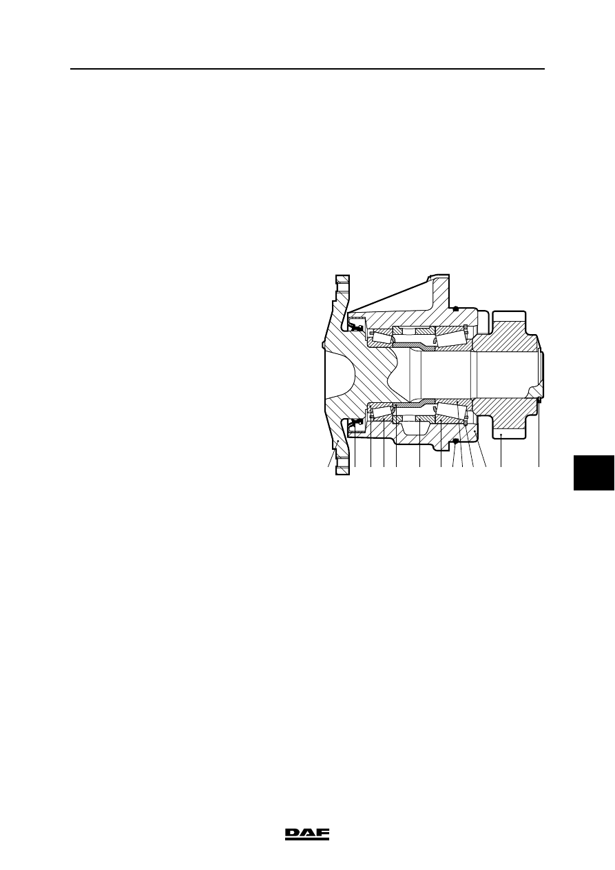
4.20 REMOVAL AND INSTALLATION, FAN DRIVE

Removing the fan drive
1.

Remove the attachment nuts from the 

viscous fan clutch. Place the viscous fan 

clutch and the fan in the wind tunnel.

2.

Remove the poly-V-belt.

3.

Remove the fan drive attachment nuts.

4.

Remove the fan drive.

Installing the fan drive
1.

Fit a new lightly greased O-ring (8) in the 

groove of the bearing housing (11).

2.

Apply engine oil to the bearings in the 

bearing housing.

3.

Fit the fan drive in the timing case. Tighten 

the attachment nuts crosswise to the 

specified torque. See "Technical data".

4.

Fit the poly-V-belt. Fit the viscous fan clutch 

with the fan.

13

8

2

1

12

3 4 5

6

7

9 10 11

M201301

XE ENGINE

4-28

©

 200324

Removal and installation

8

CF65/75/85 series

2

4.21 REMOVAL AND INSTALLATION, VIBRATION DAMPER

Removing the vibration damper
1.

Remove the poly-V-belt.

2.

Remove the attachment nuts from the 

viscous fan clutch. Place the viscous fan 

clutch and the fan in the wind tunnel.

3.

Remove the attachment bolts (9) of the fan 

pulley (6) and remove it.

4.

Remove the attachment nuts (8) of the fan 

drive and remove it.

5.

Remove the attachment bolts (5) of the 

vibration damper (4) and remove it.

Installing the vibration damper
1.

Check the vibration damper for external 

damage and silicone liquid leaks. In the 

event of damage or leaks, the vibration 

damper should be replaced.

2.

Fit the vibration damper (4). Tighten the 

attachment bolts (5) to the specified torque. 

See "Technical data".

3.

Fit the fan drive and tighten the attachment 

nuts (8) to the specified torque. See 

"Technical data".

4.

Fit the fan pulley (6). Tighten the attachment 

bolts (9) to the specified torque. See 

"Technical data".

5.

Fit the poly-V-belt.

6.

Fit the viscous fan clutch with the fan.

M201153

7

4

6

3

2
1

5

9

8

10

©

 200324

4-29

Removal and installation

XE ENGINE

CF65/75/85 series

2

8

4.22 REMOVAL AND INSTALLATION, VIBRATION DAMPER HUB

Removing the vibration damper hub
1.

Remove the vibration damper.

2.

Remove the attachment bolts from the 

vibration damper hub and remove the thrust 

piece.

}

In most cases the vibration damper 

hub will suddenly break off from the 

crankshaft during removal. Avoid 

personal injury and damage to the 

hub.

3.

Remove the vibration damper hub (1) using 

the special tool (2) (DAF no. 1453155).

Installing the vibration damper hub
1.

Fit the vibration damper hub (1) onto the 

crankshaft.

2.

Fit the thrust piece. Tighten the attachment 

bolts to the specified torque. See "Technical 

data".

3.

Install the vibration damper. Fit the thrust 

piece. Tighten the attachment bolts to the 

specified torque. See "Technical data".

M2 01 300

1

2

XE ENGINE

4-30

©

 200324

Removal and installation

8

CF65/75/85 series

2

4.23 REMOVAL AND INSTALLATION, TIMING COVER

}

When the engine or parts thereof are 

opened, dirt may enter. This may 

cause serious damage to the engine. 

Therefore, the engine should be 

cleaned thoroughly before any parts 

are opened.

Removing the timing cover
1.

Drain the coolant. See "XE engine cooling 

system".

2.

Remove the poly-V-belt.

3.

Remove the electrical connections of the 

alternator and remove the alternator bracket 

and alternator.

4.

Remove the fan drive.

5.

Remove the vibration damper.

6.

Remove the vibration damper hub using the 

special tool (DAF no. 1310422).

7.

Remove the coolant pipe.

8.

Remove the oil filler pipe.

9.

Mark the positions of the various attachment 

bolts and studs.

10. Remove the attachment bolts and studs from 

the timing cover.

11. Remove the timing cover.

12. Remove any remnants of gasket. Clean and 

inspect the sealing surfaces, dowels and 

locating holes.

13. Remove the oil seal from the timing cover.

Installing the timing cover
1.

Use three studs to position the gasket. Fit the 

new gasket.

2.

Fit the timing cover.

3.

Fit the attachment bolts and the studs. 

Tighten the attachment bolts and studs to the 

specified torque. See "Technical data".


Content   ..  254  255  256  257   ..