DAF CF65, CF75, CF85 Series . Manual - part 219


  Index      DAF     DAF CF65, CF75, CF85 Series - service repair manual


Search            


Content   ..  217  218  219  220   ..


DAF CF65, CF75, CF85 Series . Manual - part 219


©

 200324

3-1

Inspection and adjustment

PE ENGINE

CF65/75/85 series

2

5

3. INSPECTION AND ADJUSTMENT

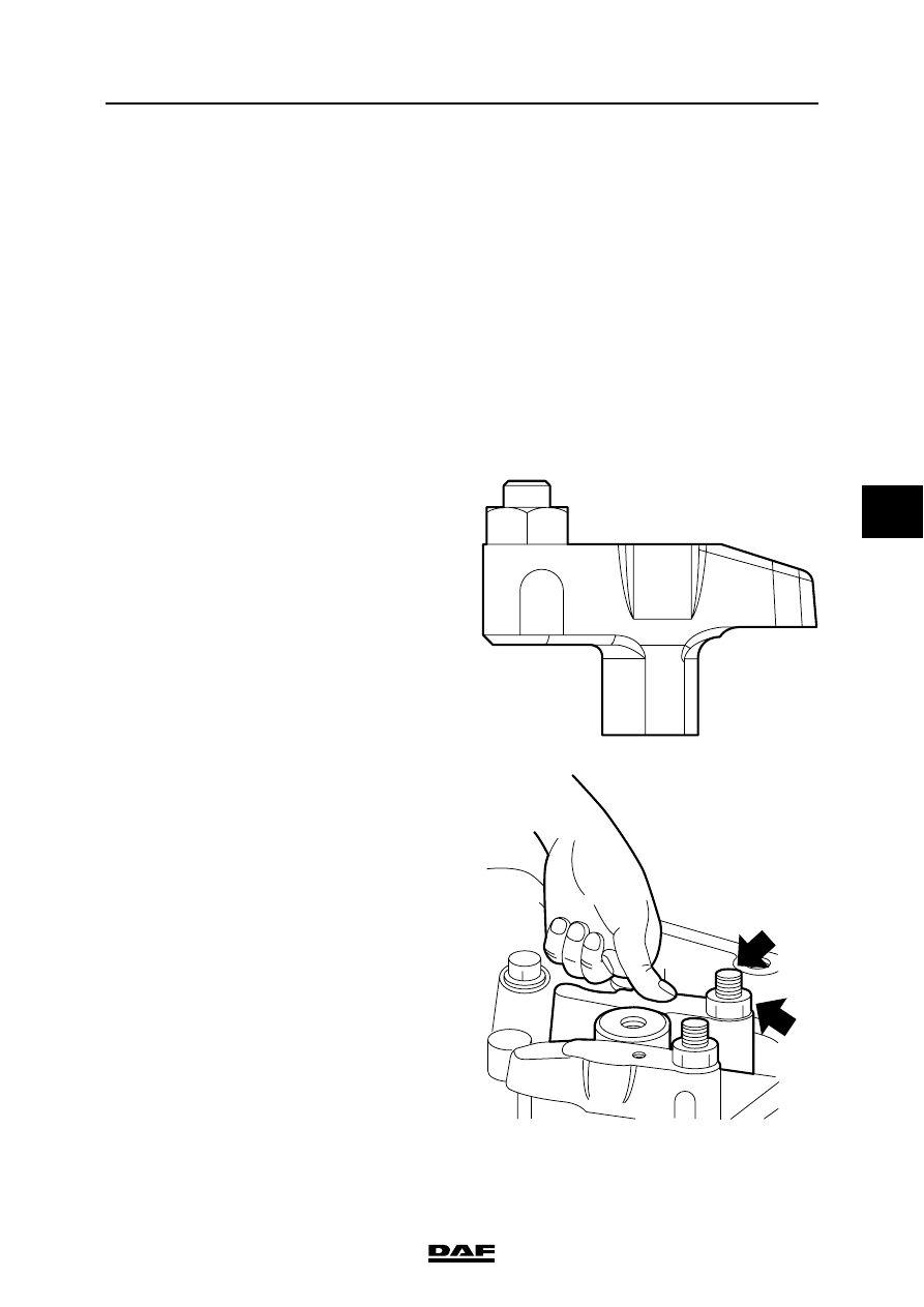
3.1 INSPECTION AND ADJUSTMENT, VALVE GEAR BRIDGES

}

Loosening and tightening the lock 

nuts (B) of the bridges may cause 

severe engine damage if the bridge 

is fitted over the valves.

1.

Remove the valve covers. See "Removal 

and installation".

2.

Undo the adjusting nuts of the valve rockers 

in such a manner that there is no longer 

tension on the rockers.

3.

Remove the lubricating oil strip.

4.

Remove the entire rocker seat. Mark the 

position to enable reinstallation in the same 

position.

5.

Remove the bridge from the valves and 

place it in a vice.

6.

Slacken the lock nut (B).

7.

Reposition the bridge in the same position in 

the engine over the valves.

8.

Firmly press on the bridge centre (above the 

guide pin) with your thumb.

9.

Hand-tighten the adjusting screw (A) until the 

bridge starts to move. The adjusting screw 

(A) now touches the valve.

10. Turn adjusting screw (A) through another 

90

° and carefully remove the bridge from the 

valves.

11. Place the bridge in a vice and tighten the lock 

nut (B) to the specified torque without turning 

the adjusting screw (A). See "Technical 

data".

12. Reposition the bridge over the valves.

i 400161

i 400301

A

B

PE ENGINE

3-2

©

 200324

Inspection and adjustment

5

CF65/75/85 series

2

13. Fit the rocker seat.

14. Fit the lubricating oil strip in such a way that 

the mark "cyl. 1/4" is at the position of 

cylinder 1 and cylinder 4 respectively.

15. Adjust the valve clearance.

16. Fit the valve covers. See "Removal and 

installation".

M200754

©

 200324

3-3

Inspection and adjustment

PE ENGINE

CF65/75/85 series

2

5

3.2 INSPECTION AND ADJUSTMENT, VALVE CLEARANCE

1.

Remove the valve covers, see chapter 

"Removal and installation".

2.

Use the special tool (DAF no. 1310477) to 

turn the crankshaft clockwise, as seen from 

the timing gear end (this corresponds with 

the engine's direction of rotation), until the 

valves of cylinder 1 are in overlap position. 

The pistons of cylinders 1 and 6 are now at 

top dead centre.

Note:

"Overlap" is the moment at which the inlet valve 

starts opening and the exhaust valve finishes 

closing.

3.

Check/correct the valve clearance of cylinder 

6. Set the correct valve clearance by 

loosening the lock nut and turning the 

adjusting screw in the correct direction. See 

main group "Technical data" for the correct 

valve clearance.

4.

By cranking the crankshaft always 1/3 

stroke, using special tool (DAF no. 1310477) 

the valves can be adjusted according to the 

injection sequence 1-5-3-6-2-4.

5.

Fit the valve covers, see chapter "Removal 

and installation".

M201185

M200733

M200732

Valves in overlap 

position

of cylinder

Adjusting valves

of cylinder

1

6

5

2

3

4

6

1

2

5

4

3

PE ENGINE

3-4

©

 200324

Inspection and adjustment

5

CF65/75/85 series

2

3.3 INSPECTION AND ADJUSTMENT, TIMING GEAR

Checking the timing gear
1.

Remove the valve cover from cylinders 1-2-

3. See "Removal and Installation".

2.

Position cylinder 1 at top dead centre (TDC 

on the flywheel, cylinder 6 in overlap 

position).

3.

Remove the timing gear cover. See 

"Removal and installation".

Note:

When the crankshaft (1) or the camshaft (2) 

of an engine is rotated separately without an 

idler gear (3), the engine's pistons may touch 

the valves.

4.

Remove the idler gear (3). See "Removal 

and installation".

5.

Now put the idler gear (3) back in such a way 

that the marks on it line up with the marks on 

the camshaft gear (2), the crankshaft gear 

(1) and the pump housing gear (4).

6.

If the marks are not in line, the timing gear 

must be adjusted.

7.

Tighten all attachment bolts that have been 

removed to the specified torque. See 

"Technical data".

M201185

M201281

2

1

3

4


Content   ..  217  218  219  220   ..