DAF CF65, CF75, CF85 Series . Manual - part 1155


  Index      DAF     DAF CF65, CF75, CF85 Series - service repair manual


Search            


Content   ..  1153  1154  1155  1156   ..


DAF CF65, CF75, CF85 Series . Manual - part 1155


©

 200423

3-3

Inspection and adjustment

EXPLANATORY NOTES ON THE MAINTENANCE ACTIVITIES

ΧΦ75 series

5

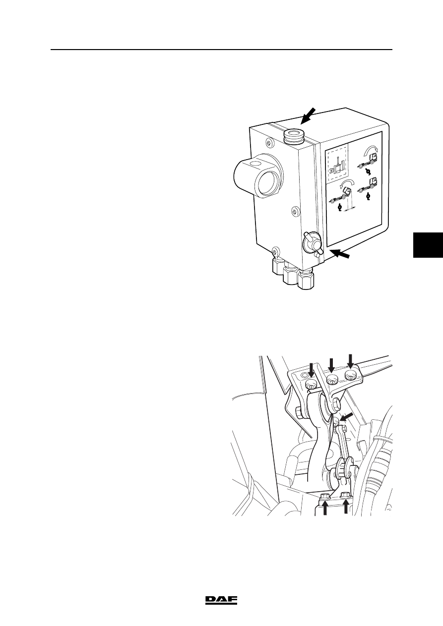
3.4 CHECKING THE FLUID LEVEL OF THE CAB TILTING PUMP

1.

The fluid level must be checked when the 

cab is in the driving position.

2.

The cock (2) should be in the "tilting back" 

position (anti-clockwise).

3.

Unscrew the filler plug (1) 3 to 4 turns. Wait 

until the overpressure, if any, has left the 

reservoir. Remove filler plug (1).

4.

Start pumping (maximum 5 pump strokes). 

Ensure that the pump lever is in the lowest 

position.

5.

Check the fluid level. This level should be no 

more than 2 cm below the top of the filling 

opening. Top up if necessary.

6.

Fit the filler plug (1) and hand tighten it.

3.5 CHECKING THE CAB FASTENING

1.

Check that all attachment bolts are in place.

2.

Visually inspect the attachment of the cab to 

the tilting mechanism.

3.

Visually inspect the seals and condition of 

the tilting mechanism.

Engine, cooling system and fuel system

M201062

N

!

1

2

K1 01 660

EXPLANATORY NOTES ON THE MAINTENANCE ACTIVITIES

3-4

©

 200423

Inspection and adjustment

5

ΧΦ75 series

3.6 INSPECTION, ENGINE OIL LEVEL

1.

Ensure that the vehicle is standing on a flat 

and level surface.

2.

Wait at least 5 minutes before checking the 

engine oil level of a hot engine.

3.

Pull the dipstick (2) out of the holder.

4.

Wipe the dipstick clean with a lint-free cloth.

5.

Put the dipstick back into the holder.

6.

Pull the dipstick out again and check the oil 

level. 

7.

If necessary, top up with oil through the filler 

opening with the red cap (C) to the maximum 

oil level.

Always use the specified oil.

Do not top up above maximum level.

Note:

For the difference between minimum and 

maximum engine oil level, see "Technical 

data".

V300384

2

V300385

C

©

 200423

3-5

Inspection and adjustment

EXPLANATORY NOTES ON THE MAINTENANCE ACTIVITIES

ΧΦ75 series

5

3.7 INSPECTION AND ADJUSTMENT, VALVE CLEARANCE

1.

Remove the valve covers, see chapter 

"Removal and installation".

2.

Use the special tool (DAF no. 1310477) to 

turn the crankshaft clockwise, as seen from 

the timing gear end (this corresponds with 

the engine's direction of rotation), until the 

valves of cylinder 1 are in overlap position. 

The pistons of cylinders 1 and 6 are now at 

top dead centre.

Note:

"Overlap" is the moment at which the inlet valve 

starts opening and the exhaust valve finishes 

closing.

3.

Check/correct the valve clearance of cylinder 

6. Set the correct valve clearance by 

loosening the lock nut and turning the 

adjusting screw in the correct direction. See 

main group "Technical data" for the correct 

valve clearance.

4.

By cranking the crankshaft always 1/3 

stroke, using special tool (DAF no. 1310477) 

the valves can be adjusted according to the 

injection sequence 1-5-3-6-2-4.

5.

Fit the valve covers, see chapter "Removal 

and installation".

M201185

M200733

M200732

Valves in overlap 

position

of cylinder

Adjusting valves

of cylinder

1

6

5

2

3

4

6

1

2

5

4

3

EXPLANATORY NOTES ON THE MAINTENANCE ACTIVITIES

3-6

©

 200423

Inspection and adjustment

5

ΧΦ75 series

3.8 CHECKING THE POLY-V-BELT

1.

Check the poly-V-belt for damage and signs 

of serious wear. 

3.9 INSPECTION AND ADJUSTMENT, V-BELT TENSION

Inspecting the V-belt tension
1.

Check the V-belt tension of the airc 

onditioning-compressor drive with the Krikit I, 

special tool (DAF no. 1240442).

2.

Set the gauge to zero by depressing the 

measuring arm (1).

3.

Place the belt tension gauge on the V-belt, 

halfway between the two pulleys.

4.

Slowly depress the V-belt by means of the 

belt-tension gauge until a click is heard. 

Then remove the belt tension gauge 

carefully. Take care not to let the measuring 

arm move. 

5.

Take the reading as indicated by the position 

of the measuring arm in relation to the scale. 

Compare this reading with the 

recommended pre-tension, see main group 

"Technical data".

1

M2061

M2062


Content   ..  1153  1154  1155  1156   ..