DAF CF65, CF75, CF85 Series . Manual - part 1092


  Index      DAF     DAF CF65, CF75, CF85 Series - service repair manual


Search            


Content   ..  1090  1091  1092  1093   ..


DAF CF65, CF75, CF85 Series . Manual - part 1092


©

 200448

2-7

Removal and installation

STABILISERS AND TORQUE RODS

ΧΦ65/75/85 series

9

4

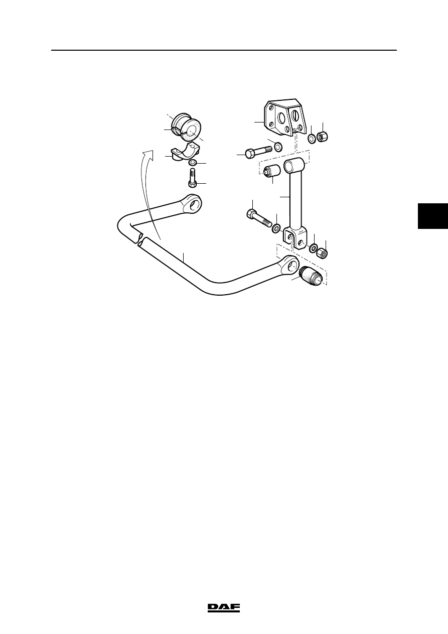
2.4 REMOVAL AND INSTALLATION, AIR-SPRUNG REAR AXLE STABILISER

Removing air-sprung rear axle stabiliser
1.

Remove the bearing bush covers (15).

2.

Remove the attachment bolts (8).

3.

Remove the stabiliser bar (13) from under 

the vehicle.

4.

Remove the bearing bushes (14) from the 

stabiliser bar (13).

5.

Remove the attachment bolts (2) and 

remove the shackle (7) from the bracket (1).

C9 00 309

13

2

3

1

4 5

6

7

8

9

10

11

16

14

15

17

12

STABILISERS AND TORQUE RODS

2-8

©

 200448

Removal and installation

4

ΧΦ65/75/85 series

9

Installing air-sprung rear axle stabiliser
1.

Check the condition of the bearing bush (14) 

and the silentblocks (6) and (12).

2.

Fit the shackle (7).

3.

Turn the bearing bushes (14) such that the 

opening is located at the contact surface of 

the bearing cover.

4.

Fit the bearing bush covers (15). Evenly 

tighten the attachment bolts (17).

5.

Fit the attachment bolts (8) with the heads 

facing towards the chassis.

©

 200448

2-9

Removal and installation

STABILISERS AND TORQUE RODS

ΧΦ65/75/85 series

9

4

2.5 REMOVAL AND INSTALLATION, LEADING REAR AXLE STABILISER

Removing leading rear axle stabiliser
1.

Remove the brackets (2) and (8).

2.

Remove the attachment bolts (10).

3.

Remove the stabiliser bar (1) from under the 

vehicle.

4.

Remove the bearing bushes (7) from the 

stabiliser bar (1).

5.

Remove the locking plate (5) and remove the 

bearing bush (4) from the axle.

Installing leading rear axle stabiliser
1.

Check the condition of the silentblock (12) 

and the bearing bushes (4) and (7).

2.

Fit bearing bush (4), using the locking 

plate (5). Tighten the attachment bolts (6) to 

the specified torque. See "Technical data".

3.

Fit the bearing bushes (7) to the stabiliser 

bar (1).

9

1

8

3

7

2

4

5

6

10

11

13

14

C9 00 313

12

STABILISERS AND TORQUE RODS

2-10

©

 200448

Removal and installation

4

ΧΦ65/75/85 series

9

4.

Turn the bearing bushes (4) and (7) into the 

indicated position.

5.

Fit the brackets (2) and (8). Fit the 

attachment bolts (3) with the heads facing 

towards the rear of the vehicle and tighten 

the bolts (3) to the specified torque, see 

"Technical data".

6.

Fit the attachment bolts (10) with the heads 

facing towards the chassis.

C9 00 312

4

7


Content   ..  1090  1091  1092  1093   ..