DAF CF65, CF75, CF85 Series . Manual - part 1065


  Index      DAF     DAF CF65, CF75, CF85 Series - service repair manual


Search            


Content   ..  1063  1064  1065  1066   ..


DAF CF65, CF75, CF85 Series . Manual - part 1065


©

 200424

2-9

General

HYDRAULIC LIFTING GEAR

ΧΦ65/75/85 series

8

9

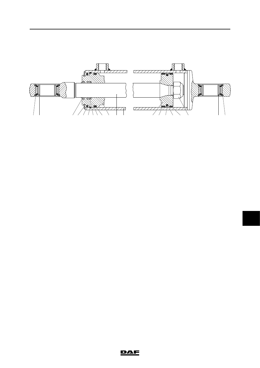
2.7 OVERVIEW DRAWING, CYLINDER

1 2

1

2

11 12

13 14 15 16 17 18

3 4 5 6

8 9

A

B

10

7

A8 00 248

1.

Circlip

2.

Bearing

3.

Dirt scraper

4.

Circlip

5.

O-ring

6.

Spring clip

7.

Sealing ring

8.

Plastic ring

9.

O-ring

10.

Piston-rod guide

11.

Piston rod

12.

Cylinder

13.

Piston

14.

Plastic ring

15.

Sealing ring

16

O-ring

17.

Plastic ring

18.

Nut

A

Pipe connection

B

Pipe connection

HYDRAULIC LIFTING GEAR

2-10

©

 200424

General

9

ΧΦ65/75/85 series

8

©

 200424

3-1

Inspection and adjustment

HYDRAULIC LIFTING GEAR

ΧΦ65/75/85 series

8

9

3. INSPECTION AND ADJUSTMENT

3.1 CHECKING THE SYSTEM PRESSURE AND PRESSURE SWITCH

1.

Make sure that the trailing axle wheels are 

fully lowered and on the ground.

2.

Connect the pressure gauge, special tool 

(DAF no. 0535653) to the pipe which is 

connected to pipe connection B by a T-piece 

(M16 x 1.5).

3.

Lift the trailing axle and take the pressure 

reading. Compare the reading with the 

technical data. See "Technical data".

The pressure switch cannot be adjusted. If 

the value deviates, the pressure switch 

should be replaced.

4.

Lower the trailing axle and remove the T-

piece and the pressure gauge.

5.

Check the oil level in the reservoir and top up 

if necessary.

A8 

00 278

HYDRAULIC LIFTING GEAR

3-2

©

 200424

Inspection and adjustment

9

ΧΦ65/75/85 series

8

3.2 INSPECTION AND ADJUSTMENT, PRESSURE RELIEF VALVE

Checking the pressure relief valve
1.

Make sure that the trailing axle wheels are 

fully lowered and on the ground.

2.

Connect the pressure gauge, special tool 

(DAF no. 0535653) to the pipe which is 

connected to pipe connection B by a T-piece 

(M16 x 1.5).

3.

Detach the pressure switch connector.

4.

Lift the trailing axle and take the pressure 

reading. Release the control switch on the 

dashboard immediately once the maximum 

pressure is achieved.

Note:

If the pressure exceeds 200 bar, the control 

switch on the dashboard should be released 

immediately.

5.

Compare the reading with the technical data. 

See "Technical data". Adjust the pressure 

relief valve if the value deviates.

6.

Fit the pressure switch connector.

7.

Lower the trailing axle and remove the T-

piece and the pressure gauge.

8.

Check the oil level in the reservoir and top up 

if necessary.

Adjusting the pressure relief valve
1.

Make sure that the trailing axle wheels are 

fully lowered and on the ground.

2.

Connect the pressure gauge, special tool 

(DAF no. 0535653) to the pipe which is 

connected to pipe connection‚ B by a T-piece 

(M16 x 1.5).

3.

Detach the pressure switch connector.

4.

Loosen the lock nut (2) of the pressure relief 

valve (3).


B

A

A8 00 281

A8 00 280


Content   ..  1063  1064  1065  1066   ..