Content .. 1061 1062 1063 1064 ..
DAF CF65, CF75, CF85 Series . Manual - part 1063
©
200424
2-1
General
HYDRAULIC LIFTING GEAR
ΧΦ65/75/85 series
8
9
2. GENERAL
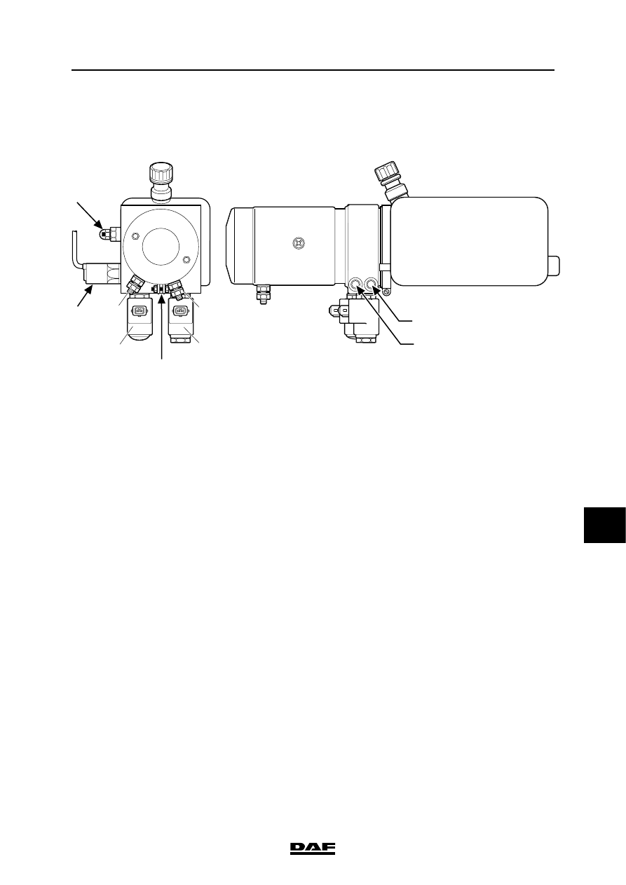
2.1 LOCATION OF COMPONENTS
Relays, diodes and fuse
The relay, diodes and fuse that have a bearing on
the lifting gear of the trailing axle are stored in a
watertight box.
This box is fitted on the inside of the chassis on
the chassis main member.
A
B
1
2
3
4
5
6
7
A8 00 247
1.
Pressure switch
2.
Pressure relief valve
3.
4/2 solenoid valve (lift trailing axle)
4.
2/2 solenoid valve (lower trailing axle)
5.
Built-in non-return valve
6.
+ connection point (D1E1)
7.
- connection point (D2E2)
A.
Line connection (delivery line while
lowering)
B.
Line connection (delivery line while lifting)
(The characters are imprinted on the
pump unit)