DAF CF65, CF75, CF85 Series . Manual - part 1038


  Index      DAF     DAF CF65, CF75, CF85 Series - service repair manual


Search            


Content   ..  1036  1037  1038  1039   ..


DAF CF65, CF75, CF85 Series . Manual - part 1038


©

 200424

3-11

Removal and installation

SINGLE REAR AXLE 1354

ΧΦ65/75/85 series

8

5

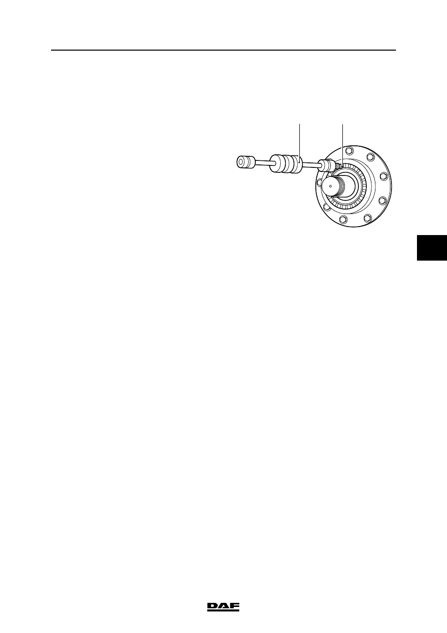
3.7 REMOVAL AND INSTALLATION, PINION OIL SEAL

Removing the pinion oil seal
1.

Remove the drive flange.

2.

Drill two holes into the seal and screw the 

special tool (B) (DAF no. 0484899) into the 

seal. Pull the oil seal from the pinion housing 

using the special tool (A) 

(DAF no. 0694928).

Installing the pinion oil seal
1.

Use the special tool (DAF no. 1240088) to fit 

the seal so that the inscription "outside" is 

pointed outwards.

2.

Fit the drive flange.

A

B

A8 00 426

SINGLE REAR AXLE 1354

3-12

©

 200424

Removal and installation

5

ΧΦ65/75/85 series

8

3.8 REMOVAL AND INSTALLATION, DIFFERENTIAL

Removing the differential
1.

Drain the oil from the differential and the 

hubs, see Chapter "Draining and filling".

2.

Remove the prop shaft from the drive flange.

3.

Remove the left axle shaft.

4.

Pull the right axle shaft (i.e. on the side 

where the differential-gear lock cylinder is 

fitted) 15 - 18 cm from the hub.

5.

Remove the air connection for the differential 

lock.

6.

Slacken the locking nut of the differential lock 

cylinder and turn the differential lock cylinder 

out approx. one turn.

7.

Attach the differential securely to a lifting 

device.

8.

Remove the attachment bolts from the 

differential.

9.

Remove the differential from the axle 

housing using two jacking screws.

A800291

1

2

3

4

6 5

7

8

9

1110

12

13

14

15

16

17

18

19

20

21

22

23

24

©

 200424

3-13

Removal and installation

SINGLE REAR AXLE 1354

ΧΦ65/75/85 series

8

5

Installing the differential
1.

Install the right axle shaft and slide it into the 

selector sleeve of the differential lock 

cylinder.

2.

Slacken the engaging cylinder until the 

selector sleeve is positioned inside the edge 

of the axle housing.

3.

Remove the jacking screws.

4.

Clean the mating surfaces of the banjo 

housing and the differential housing and 

regrind the surfaces lightly. Do not damage 

the mating faces in the process.

5.

Check the stud bolts for signs of damage. 

Replace the stud bolts if these are damaged. 

Apply locking compound to the new stud 

bolts, see "Technical data".

6.

Apply a thin, even layer of sealant to the 

mating surface and around the stud bolts of 

the banjo housing, see "Technical data".

7.

Fit the differential into the banjo housing. 

Evenly tighten the nuts. Tighten the nuts to 

the specified tightening torque, see 

"Technical data".

8.

Install the left axle shaft and slide both axle 

shafts into the differential.

9.

Tighten the engaging cylinder while turning 

the right wheel at the same time, until the 

teeth of the selector sleeve and the satellite-

gear housing engage.

10. Slacken the engaging cylinder 1.5 turns and 

tighten the lock nut to the specified tightening 

torque, see "Technical data".

11. Fit the air connection to the differential lock.

12. Fit the prop shaft to the drive flange.

13. Fill the differential and the hubs with oil. See 

"Draining and filling".

A800024

A800035

A800034

1,5x

SINGLE REAR AXLE 1354

3-14

©

 200424

Removal and installation

5

ΧΦ65/75/85 series

8

3.9 REMOVAL AND INSTALLATION, DIFFERENTIAL LOCK

Removing the differential lock
1.

Remove the differential.

2.

Remove the yoke axle (5) from the yoke (6) 

using a home-made yoke puller (A800151).

ø30

ø30

ø16

ø9

M8   

165

120

6

A800151

A800026


Content   ..  1036  1037  1038  1039   ..