DAF XF105. Manual - part 82
0
©
200528
1-33
DMCI engine management system
TECHNICAL DATA
XF105 series
1.20 EXHAUST BRAKE VALVE
A
C
B
i400726
1
4
5
9
13
17
21
25
29
33
37
41
45
49
53
57
60
62
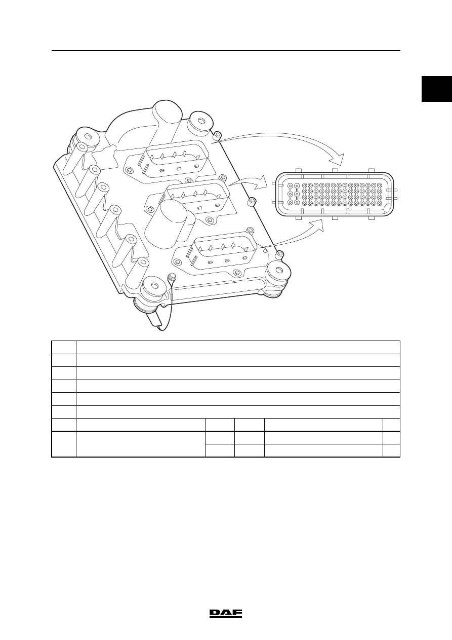
A
Electronic unit connection point
B
Description of connection point
C
Reading at connection point (Ubat = battery voltage)
D
Measuring unit
E
Explanatory notes (if applicable)
F
Additional information available in Technical Data at "X" mark
A
B
C
D
E
F
C28
Output signal exhaust brake valve
(B192)
Ubat
VDC
Exhaust brake valve not active
0
VDC
Exhaust brake valve active
Resistance value
56
≥ 10%