Chrysler Town, Dodge Caravan. Manual - part 528


  Index      Chrysler     Chrysler TOWN & COUNTRY, VOYAGER, Dodge Caravan - service repair manual 2001-2007 year


Search            


Content   ..  526  527  528  529   ..


Chrysler Town, Dodge Caravan. Manual - part 528


(8) Tighten the two M8 fasteners at the rail to 23

Nm (17 ft. lbs.). Taking care so that the exhaust tube
bracket tab is on the top of the heater bracket.

(9) Install the wiring harness(Refer to 24 - HEAT-

ING

&

AIR

CONDITIONING/CABIN

HEATER/

HEATER UNIT - INSTALLATION).

(10) Tighten the hose and tube assembly to the

toe-board cross member at two locations.

(11) Install the second hose to the underbody hose

and tube assembly.

(12) Connect the rubber fuel hose between the

body tube assembly and the fuel pump nipple at the
body tube joint. Close the fuel fill cap.

(13) Remove the heater unit support device from

under the vehicle.

(14) Lower vehicle from lift.
(15) Refill cooling system(Refer to 7 - COOLING -

STANDARD PROCEDURE).

(16) Verify function of the cabin heater.

SUPPLEMENTAL DIESEL
HEATER WIRING

REMOVAL

(1) Elevate vehicle on a lift taking note of the

exhaust tube flexible section.

(2) Unplug connector from vehicle wiring harness

to cabin heater harness.

(3) Unplug connector from cabin heater harness to

dosing pump connector.

(4) Unplug two connectors from cabin heater har-

ness to cabin heater controller connectors.

(5) Remove two wiring harness connectors from

underbody.

(6) Remove two wiring harness connectors from

cabin heater shield.

(7) Carefully route the cabin heater harness to the

left side between the cabin heater unit and the cabin
heater shield.

INSTALLATION

(1) Carefully route the cabin heater harness from

the left side of the cabin heater between the cabin
heater unit and the cabin heater shield.

(2) Install the two wiring harness retaining con-

nectors to the cabin heater shield.

(3) Route the wiring harness along the underside

of the vehicle and install the two wiring harness
retaining connectors.

(4) Plug the two connectors from the cabin heater

harness to the cabin heater controller.

(5) Plug the connector to the cabin heater harness

to the dosing pump connector.

(6) Plug the connector from the vehicle wiring har-

ness to the cabin heater harness.

(7) Lower the vehicle.
(8) Verify function of the cabin heater.

AIR INTAKE PIPE

REMOVAL

NOTE: Heater air intake tube is part of an assembly
that includes the heater cooling intake and return
pipes. If heater air intake tube requires removal or
replacement the entire assembly will require remov-
al/replacement.

(1) Drain cooling system(Refer to 7 - COOLING -

STANDARD PROCEDURE).

(2) Remove clamps from the heater tubes at the

lower heater port and the lower EGR connector
which are located under the hood.

(3) Remove the retaining clamp at the heater air

intake muffler connection(Refer to 24 - HEATING &
AIR

CONDITIONING/CABIN

HEATER/INLET

MUFFLER - REMOVAL).

(4) Remove the clamp at the flexible tube to steel

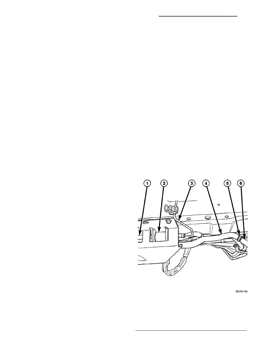
tube connection (Fig. 4).

Fig. 4 FLEXIBLE AIR INTAKE LINE

1 - HEATER UNIT AND SPLASH SHIELD
2 - DOSING PUMP
3 - DOSING PUMP FUEL LINE
4 - FLEXIBLE INTAKE LINE
5 - CLAMP
6 - STEEL INTAKE PIPE

24 - 112

DIESEL SUPPLEMENTAL HEATER - DCHA - EXPORT

RS

HEATER UNIT (Continued)

(5) Remove the two retaining screws and remove

pipe assembly (Fig. 5).

INSTALLATION

(1) Install the air intake pipe assembly and install

the two retaining screws. Tighten the screws to 7 Nm
( 5 ft. lbs.).

(2) Attach the steel tube to the flexible tube and

position and then tighten the retaining clamp.

(3) Install the flexible tube to the heater air intake

muffler and install and tighten the retaining clamp.

(4) Install the heater tubes to the lower heater

connection and the lower EGR cooler connection and
tighten the retaining clamps.

(5) Lower the vehicle.
(6) Refill the cooling system(Refer to 7 - COOLING

- STANDARD PROCEDURE).

(7) Verify function of the heater unit.

Fig. 5 AIR INTAKE AND HEATER PIPE ASSEMBLY

1 - INTAKE TUBE AIR INTAKE
2 - INTAKE PIPE
3 - RETAINING SCREWS
4 - INTAKE HEATER LINE
5 - RETURN HEATER LINE

RS

DIESEL SUPPLEMENTAL HEATER - DCHA - EXPORT

24 - 113

AIR INTAKE PIPE (Continued)

EMISSIONS CONTROL

TABLE OF CONTENTS

page

page

EMISSIONS CONTROL

DESCRIPTION

DESCRIPTION - VEHICLE EMISSION

CONTROL INFORMATION LABEL . . . . . . . . . . 1

DESCRIPTION - TRIP DEFINITION

. . . . . . . . . 1

DESCRIPTION - MONITORED COMPONENT

. 1

OPERATION - NON-MONITORED CIRCUITS

. . 5

DESCRIPTION - MONITORED SYSTEMS

. . . . 6

DESCRIPTION - HIGH AND LOW LIMITS

. . . . 8

OPERATION

OPERATION - SYSTEM

. . . . . . . . . . . . . . . . . . 9

DRB III

T

STATE DISPLAY TEST MODE

. . . . . . 9

EVAPORATIVE EMISSIONS

. . . . . . . . . . . . . . . . 10

EXHAUST GAS RECIRCULATION

. . . . . . . . . . . 21

ON-BOARD DIAGNOSTICS

. . . . . . . . . . . . . . . . 24

EMISSIONS CONTROL

DESCRIPTION

DESCRIPTION - VEHICLE EMISSION CONTROL
INFORMATION LABEL

All models have a Vehicle Emission Control Infor-

mation (VECI) Label. Chrysler permanently attaches
the label in the engine compartment. It cannot be
removed without defacing information and destroying
the label.

The label contains the vehicle’s emission specifica-

tions and vacuum hose routings. All hoses must be
connected and routed according to the label.

DESCRIPTION - TRIP DEFINITION

A “Trip” means vehicle operation (following an

engine-off period) of duration and driving mode such
that all components and systems are monitored at
least once by the diagnostic system. The monitors
must successfully pass before the PCM can verify
that a previously malfunctioning component is meet-
ing the normal operating conditions of that compo-
nent. For misfire or fuel system malfunction, the
MIL may be extinguished if the fault does not recur
when monitored during three subsequent sequential
driving cycles in which conditions are similar to
those under which the malfunction was first deter-
mined.

Anytime the MIL is illuminated, a DTC is stored.

The DTC can self erase only after the MIL has been
extinguished. Once the MIL is extinguished, the
PCM must pass the diagnostic test for the most
recent DTC for 40 warm-up cycles (80 warm-up
cycles for the Fuel System Monitor and the Misfire
Monitor). A warm-up cycle can best be described by
the following:

• The engine must be running

• A rise of 40°F in engine temperature must occur

from the time when the engine was started

• Engine coolant temperature must crossover

160°F

• A “driving cycle” that consists of engine start up

and engine shut off.

Once the above conditions occur, the PCM is con-

sidered to have passed a warm-up cycle. Due to the
conditions required to extinguish the MIL and erase
the DTC, it is most important that after a repair has
been made, all DTC’s be erased and the repair veri-
fied by running 1–good trip.

DESCRIPTION - MONITORED COMPONENT

There are several components that will affect vehi-

cle emissions if they malfunction. If one of these com-
ponents

malfunctions

the

Malfunction

Indicator

Lamp (Check Engine) will illuminate.

Some of the component monitors are checking for

proper operation of the part. Electrically operated
components now have input (rationality) and output
(functionality) checks. Previously, a component like
the Throttle Position sensor (TPS) was checked by
the PCM for an open or shorted circuit. If one of
these conditions occurred, a DTC was set. Now there
is a check to ensure that the component is working.
This is done by watching for a TPS indication of a
greater or lesser throttle opening than MAP and
engine rpm indicate. In the case of the TPS, if engine
vacuum is low and engine rpm is 1600 or greater and
the TPS indicates a small throttle opening, a DTC
will be set.

Any component that has an associated limp in will

set a fault after 1 trip with the malfunction present.

Refer to the Diagnostic Trouble Codes Description

Charts (Refer to 8 - ELECTRICAL/ELECTRONIC
CONTROL

MODULES/POWERTRAIN

CONTROL

MODULE - DESCRIPTION) and the appropriate
Powertrain Diagnostic Procedure Manual for diag-
nostic procedures.

RS

EMISSIONS CONTROL

25 - 1


Content   ..  526  527  528  529   ..