Chrysler Town, Dodge Caravan. Manual - part 526


  Index      Chrysler     Chrysler TOWN & COUNTRY, VOYAGER, Dodge Caravan - service repair manual 2001-2007 year


Search            


Content   ..  524  525  526  527   ..


Chrysler Town, Dodge Caravan. Manual - part 526


REMOVAL

REMOVAL - REAR HEATER LINES

(1) Raise and support vehicle.
(2) Pinch off rubber heater line hose.
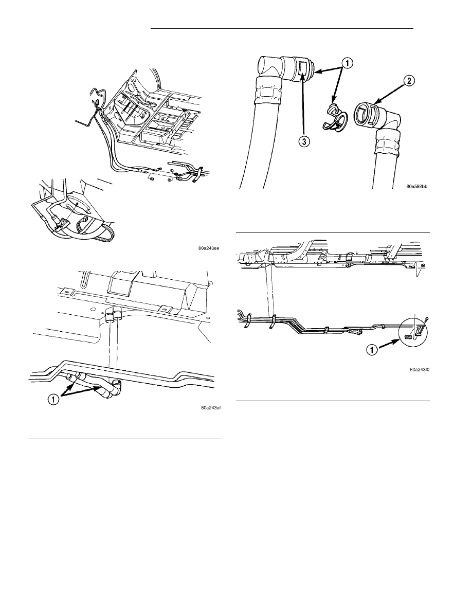
(3) Disconnect quick connect fitting at C-pillar.
(4) Loosen one screw and remove the other screw

at each of the three brackets holding the front of the
line to the underbody.

(5) Lower rear of line and drain coolant into a

suitable container.

(6) Loosen hose clamps at front of line and remove

line from vehicle.

REMOVAL - REAR AIR CONDITIONING LINES

(1) Recover A/C system.
(2) Hoist and support vehicle.
(3) Loosen one screw and remove the other screw

at each of the three brackets holding the A/C lines to
the underbody (Fig. 9).

(4) Remove both A/C lines from the two rear

retaining clamps, behind rear wheel.

(5) Remove both compression fittings at front of

A/C lines (Fig. 10).

(6) Remove (1) bolt securing A/C lines to block

located at A/C housing, behind rear wheel, and sepa-
rate block (Fig. 13).

(7) Remove rear wheel.
(8) Separate ABS harness from flex hose clamps.
(9) Remove heater lines from underbody brackets.
(10) Pinch off rubber heater line hoses at front of

vehicle.

Fig. 10 Front Lines Connected to Rear Lines

Fig. 11 Rear Heater Hose Connection

1 - REAR HEATER HOSE

Fig. 12 Rear heater hose quick connects

1 - INSERT
2 - QUICK CONNECT
3 - COMPRESS INSERT FOR REMOVAL

Fig. 13 Rear A/C Block Connection

1 - CLEAN AREA AROUND BLOCK BEFORE REMOVAL

24 - 104

PLUMBING - REAR

RS

UNDERBODY LINES (Continued)

(11) Loosen hose clamps at front of heater lines

and allow them to hang from vehicle.

(12) Remove rear A/C lines from vehicle.
(13) Remove nylon wedge holding lines into rear

block (Fig. 14).

INSTALLATION

INSTALLATION - REAR HEATER LINES

(1) Install line into underbody straps.
(2) Install line into front hose and install hose

clamp.

(3) Connect quick fitting at rear of line.
(4) Lower vehicle.
(5) Fill cooling system (Refer to 7 - COOLING -

STANDARD PROCEDURE).

INSTALLATION - REAR AIR CONDITIONING
LINES

(1) Before installation, replace all O-rings and gas-

kets. Coat all sealing surfaces with approved wax-
free refrigerant oil.

(2) Install A/C line into rear block with nylon

wedge.

(3) Install A/C lines into five underbody brackets.
(4) Connect forward compression fittings.
(5) Install bolt at sealing block to rear A/C hous-

ing.

(6) Install ABS harness into clips.
(7) Install heater hoses into underbody brackets.
(8) Install lines into front hoses and install hose

clamps.

(9) Lower vehicle.
(10) Evacuate and recharge system.
(11) Fill cooling system (Refer to 7 - COOLING -

STANDARD PROCEDURE).

Fig. 14 UNDERBODY LINE WEDGES

1 - O-RING
2 - DISCHARGE LINE
3 - NYLON WEDGE
4 - SEALING BLOCK
5 - VISE
6 - SUCTION LINE

RS

PLUMBING - REAR

24 - 105

UNDERBODY LINES (Continued)

DIESEL SUPPLEMENTAL HEATER - DCHA - EXPORT

TABLE OF CONTENTS

page

page

DIESEL SUPPLEMENTAL HEATER - DCHA -

EXPORT
DESCRIPTION

. . . . . . . . . . . . . . . . . . . . . . . . 106

OPERATION

OPERATION

. . . . . . . . . . . . . . . . . . . . . . . . 106

OPERATION - TWO ZONE ATC

. . . . . . . . . . 106

DIAGNOSIS AND TESTING - DIESEL

SUPPLEMENTAL HEATER - DCHA

. . . . . . . 107

EXHAUST TUBE

REMOVAL

. . . . . . . . . . . . . . . . . . . . . . . . . . . . 107

INSTALLATION

. . . . . . . . . . . . . . . . . . . . . . . . 107

FUEL DOSING PUMP

DESCRIPTION

. . . . . . . . . . . . . . . . . . . . . . . . 108

OPERATION

. . . . . . . . . . . . . . . . . . . . . . . . . . 108

REMOVAL

. . . . . . . . . . . . . . . . . . . . . . . . . . . . 108

INSTALLATION

. . . . . . . . . . . . . . . . . . . . . . . . 108

FUEL LINE

STANDARD PROCEDURE - CLEANING

. . . . . 109

REMOVAL

. . . . . . . . . . . . . . . . . . . . . . . . . . . . 109

INSTALLATION

. . . . . . . . . . . . . . . . . . . . . . . . 110

HEATER UNIT

REMOVAL

. . . . . . . . . . . . . . . . . . . . . . . . . . . . 111

INSTALLATION

. . . . . . . . . . . . . . . . . . . . . . . . 111

SUPPLEMENTAL DIESEL HEATER WIRING

REMOVAL

. . . . . . . . . . . . . . . . . . . . . . . . . . . . 112

INSTALLATION

. . . . . . . . . . . . . . . . . . . . . . . . 112

AIR INTAKE PIPE

REMOVAL

. . . . . . . . . . . . . . . . . . . . . . . . . . . . 112

INSTALLATION

. . . . . . . . . . . . . . . . . . . . . . . . 113

DIESEL SUPPLEMENTAL
HEATER - DCHA - EXPORT

DESCRIPTION

Vehicles equipped with the optional diesel engine

are also equipped with a supplemental heater unit.
This unit is mounted under the vehicle and operates
similar to an oil fired furnace. The heater burns
small amounts of fuel to provide additional heat to
the coolant. Coolant is routed from the engine, to the
supplemental heater, and then to the front heater
core. This provides additional heat to the passenger
compartment. The system is interfaced to the vehi-
cles on-board computer systems and DRB-III diag-
nostics.

The supplemental heater unit has a electronic con-

trol unit that monitors the heat output of the heater.
The heater operates at full load (5 kW), half load or
idle mode (no additional heat) depending on collant
temperature.

OPERATION

OPERATION

The supplemental heater unit is activated via the

temperature slide control or knob on the vehicle
HVAC control unit. If the control slide or knob is
moved to or above the upper set point the heater is
activated. The unit can operate in a full or partial
load range as well as an idle mode all dependent on
the engine coolant temperature. The heater unit will

also turn off if the HVAC temperature control is low-
ered to less than the lower set point. The heater unit
can take up to three minutes to completely shut
down when either the heater temperature is set
below the lower set point or the vehicle ignition is
shut down.

The supplemental heater only operates when the

engine is running, the mileage exceeds 8 kilometer (5
mph) and the fuel tank volume exceeds 1/8 of a tank.
The heater should start if the collant temperature is
below 40 degrees celsius (104 degrees F).

NOTE: Do not apply a strong vacuum directly on
the supplemtal heater exhaust line. Place the vac-
uum within 75 mm (3 inches) of the exhaust port.
Too strong of a vacuum can prevent the heater from
starting. The heater ECU monitors the supplemental
blower speed and combustion during its start-up.

OPERATION - TWO ZONE ATC

The Two Zone ATC control head will activate the

Supplemental Heater based on engine coolant tem-
perature and interior component settings. The unit
can operate in a full or partial load range as well as
an idle mode all dependent on the engine coolant
temperature. The unit will also turn off if the HVAC
temperature control setting is lowered to less than
the lower set point. The unit can take up to three
minutes to completely shut down when either the
heater temperature is set below the lower set point of
the vehicle ignition is shut down.

24 - 106

DIESEL SUPPLEMENTAL HEATER - DCHA - EXPORT

RS

The supplemental heater only operates when the

engine is running, the mileage exceeds 8 kilometers
(5 mph) and the fuel tank volume exceeds 1/8 of a
tank. The heater should start if the coolant temper-
ature is below 40 degrees celsius (104 degrees F).

NOTE: Do not apply a strong vacuum directly on
the supplemental heater exhaust line. Place the vac-
uum within 75 mm (3 inches) of the exhaust outlet
port. Too strong of a vacuum can prevent the heater

from starting. The heater ECU monitors the supple-
mental blower speed and combustion during its
start-up.

DIAGNOSIS AND TESTING - DIESEL
SUPPLEMENTAL HEATER - DCHA

The following table lists possible fault symptoms of

diesel fueled heaters.

SYMPTOM

POSSIBLE CAUSES

Smell of diesel fuel

Check heater system integration in vehicle’s fuel system. Check fuel
lines for leakage, kinks or obstructions. If OK, Inspect the inlet muffler,
drain as necessary. Re-test the unit and re-inspect. Inspect the
exhaust tube and heater unit for the presence of external fuel. If a
volume is observed on the unit or in the exhaust tube or after draining
and testing. Remove heater unit from vehicle and repair or replace
components as required.

Heater does not achieve full load
operation.

Check heater operation with DRB-III and replace components as
required.

Continuous white smoke from heater
exhaust during combustion operation.

Check heater operation with DRB-III and replace components as
required. White smoke is typical in extreme weather conditions.

Heater can not be switched off.

Check heater operation with DRB-III and replace components as
required.

Heater does not operate.

Diagnosis cabin heater ECU using the DRB-III and the procedures
listed in Vehicle Performance under Cabin Heater Diagnosis in Group
18.

Loss of coolant (Leakage) or heater
develops smoke during combustion
operation and exhaust has an
extremely sweet smell.

Inspect coolant hoses for leakage, kinks or loose hose connection.
Inspect the exhaust tube assembly for continuous flow, if OK there is
an internal heater leak and unit should be inspected and components
should be replaced as required.

Loss of fuel (dripping).

Check heater system integration in vehicles fuel system. Check fuel
line connection for leakage. If OK there is an internal leak and unit
should be inspected and replaced as required.

EXHAUST TUBE

REMOVAL

WARNING: THERE IS A POTENTIAL DANGER OF
SKIN BURNS AS THE HEATER AND ITS COMPO-
NENTS MAY BE VERY HOT. MAKE SURE THE
HEATER IS ALLOWED TO COOL DOWN BEFORE
ANY SERVICE WORK ON THE CABIN HEATER SYS-
TEM IS ATTEMPTED.

(1) Elevate vehicle on a lift taking note of the

exhaust tube flexible section.

(2) Remove the exhaust clamp at the flexible pipe

and steel pipe connection (Fig. 1).

(3) Remove the clamp at the flexible pipe connec-

tion and the heater unit housing (if required).

(4) Remove the three screws holding the exhaust

pipe to the body.

(5) Remove the steel exhaust pipe from the vehi-

cle.

(6) Remove the flexible exhaust pipe from the

vehicle (if required).

INSTALLATION

(1) Install the flexible exhaust pipe to the heater

unit. Tighten mounting clamp.

(2) Position the steel exhaust pipe to the flexible

exhaust and install and tighten the mounting clamp.

(3) Install the three exhaust pipe screws, adjust

pipe placement as needed and tighten the screws.

(4) Install the clamp to connect the steel exhaust

pipe to the flexible exhaust pipe and tighten clamp.

RS

DIESEL SUPPLEMENTAL HEATER - DCHA - EXPORT

24 - 107

DIESEL SUPPLEMENTAL HEATER - DCHA - EXPORT (Continued)


Content   ..  524  525  526  527   ..