Chrysler Town, Dodge Caravan. Manual - part 527


  Index      Chrysler     Chrysler TOWN & COUNTRY, VOYAGER, Dodge Caravan - service repair manual 2001-2007 year


Search            


Content   ..  525  526  527  528   ..


Chrysler Town, Dodge Caravan. Manual - part 527


(5) Check exhaust pipe exhaust end placement and

make any final adjustments.

(6) Lower vehicle from lift.

FUEL DOSING PUMP

DESCRIPTION

The dosing pump is a combined delivery, dosing

and shut-off system for the fuel supply to the heater
from the vehicles fuel tank.

OPERATION

The dosing pump is an electrically operated pump

that receives its operation instructions from the sup-
plemental heater electronic control module. The
pump supplies diesel fuel from the fuel tank to the
heater unit.

REMOVAL

The dosing pump is serviceable without removing

the component from the vehicle.

(1) Disconnect the rubber hose at the fuel line to

heater fuel pump. Leave the rubber hose on the fuel
line.(Refer to 24 - HEATING & AIR CONDITION-

ING/CABIN HEATER/FUEL LINE - REMOVAL)
(Fig. 2).

(2) Disconnect the fuel line between the dosing

pump and the heater unit.

NOTE: Position and retain heater fuel line to pre-
vent fuel leakage while servicing dosing pump.

NOTE: Utilize an approved fuel storage container to
catch any residual fuel.

(3) Disconnect the electrical connector to the fuel

pump by depressing the integral spring and pulling
the connector away from the pump.

(4) Remove the dosing pump from the rubber iso-

lation.

INSTALLATION

(1) Mount the rubber isolation back onto the

splash shield mounting flanges at two locations.

(2) Connect fuel lines to the dosing pump and the

heater unit. The connectors should point towards the
heater fuel line.

(3) Use aviation style clamps to attach the hose to

the fuel pump nipples(Refer to 24 - HEATING & AIR

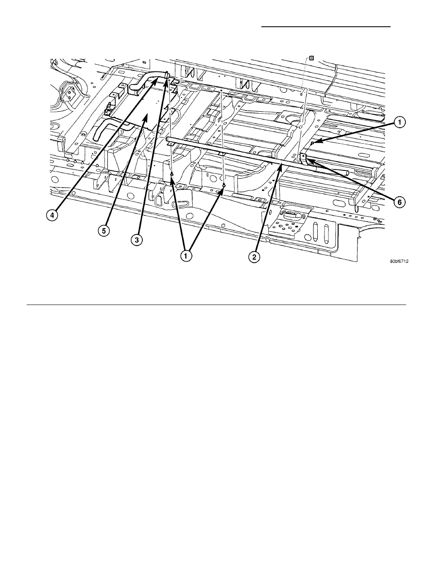
Fig. 1 Diesel Cabin Heater Exhaust System

1 - Mounting screws (3)
2 - Steel heater exhaust pipe
3 - Exhaust clamp (2)

4 - Flexible heater exhaust pipe
5 - Heater and heater shield
6 - Exhaust pipe mounting clips (3) (If Equipped)

24 - 108

DIESEL SUPPLEMENTAL HEATER - DCHA - EXPORT

RS

EXHAUST TUBE (Continued)

CONDITIONING/CABIN

HEATER/FUEL

LINE

-

INSTALLATION).

(4) Connect the electrical connector to the fuel

pump by depressing the integral spring and pushing
the connector towards the dosing pump. Pull the con-
nector towards the heater to verify the installation.

(5) Verify function of the heater.

FUEL LINE

STANDARD PROCEDURE - CLEANING

(1) Remove the cabin heater fuel line(Refer to 24 -

HEATING & AIR CONDITIONING/CABIN HEAT-
ER/FUEL LINE - REMOVAL).

(2) With cabin heater line removed from vehicle

place a shop cloth on the fuel tank end of the fuel
line to catch any residue, then apply a small amount
of air pressure to the other end of the fuel line.

(3) Check to see if air pressure is coming from the

tank end of the line. If pressure is flowing unre-
stricted the line is clean.

(4) If the line shows any signs of being restricted

after air pressure is applied, then the fuel line should
be replaced.

(5) Install the cabin heater line(Refer to 24 -

HEATING & AIR CONDITIONING/CABIN HEAT-
ER/FUEL LINE - INSTALLATION).

(6) Verify function of the heater.

REMOVAL

(1) Elevate vehicle on a lift taking note of the

heater exhaust tube flexible section.

(2) Remove clamps on dosing pump end of fuel line

and separate line from pump (Fig. 3).

NOTE: Have an approved fuel holding device ready
to capture any diesel fuel that drains from fuel line
or heater unit.

(3) Remove clamp from fuel line at fuel tank con-

nection and separate line from tank.

(4) Remove any retaining clips and remove line

from vehicle.

Fig. 2 Dosing Pump Fuel Line

1 - Fuel Line
2 - Retaining Clamps

3 - Dosing Pump
4 - Heater Unit Air Intake Pipe

RS

DIESEL SUPPLEMENTAL HEATER - DCHA - EXPORT

24 - 109

FUEL DOSING PUMP (Continued)

INSTALLATION

WARNING: DO NOT OPERATE THE DCHA IN AN
ENCLOSED AREA SUCH AS A GARAGE THAT
DOES NOT HAVE EXHAUST VENTILATION FACILI-
TIES. ALWAYS VENT THE DCHA’S EXHAUST WHEN
OPERATING THE DCHA. FAILURE TO FOLLOW
THESE INSTRUCTIONS MAY RESULT IN PERSONAL
INJURY OR DEATH.

WARNING: ALLOW

THE

DCHA ASSEMBLY

TO

COOL

BEFORE

PERFORMING

A

COMPONENT

INSPECTION/REPAIR/REPLACEMENT. FAILURE TO
FOLLOW THESE INSTRUCTIONS MAY RESULT IN
PERSONAL INJURY.

WARNING: VERIFY THAT ALL DCHA FUEL LINES
ARE SECURELY FASTENED TO THEIR RESPECTIVE
COMPONENTS BEFORE PERFORMING THIS PRO-
CEDURE.

NOTE: Verify that there is more than 1/8 of a tank of
fuel in the vehicle’s fuel tank before performing this
procedure. Add fuel, if necessary.

(1) Install heater fuel supply line to vehicle and

install in fuel line retainers

(2) Install fuel line connection at fuel tank and

tighten connection.

(3) Install fuel line at Dosing Pump and tighten

connection.

(4) Lower vehicle from lift.

NOTE: Failure to prime the Dosing Pump after
draining the DCHA fuel line will prevent DCHA
heater activation during the first attempt to start the
heater. This will also set a Diagnostic Trouble Code
(DCT) in the DCHA Control’s memory. Do not per-
form the Dosing Pump Priming procedure if an
attempt was made to start the DCHA without prim-
ing the Dosing Pump first. This will put excess fuel
in the DCHA Heater Module and cause smoke to
emit from the DCHA exhaust pipe when heater acti-
vation occurs.

(5) Connect the DRBIII

t to the Diagnostic Link

Connector.

(6) Turn the ignition to the on position.

Fig. 3 Dosing Pump Fuel Line

1 - Fuel Line
2 - Retaining Clamps

3 - Dosing Pump
4 - Heater Unit Air Intake Pipe

24 - 110

DIESEL SUPPLEMENTAL HEATER - DCHA - EXPORT

RS

FUEL LINE (Continued)

NOTE: Do not activate the Dosing Pump Prime
more than one time. This will put excess fuel in the
DCHA Heater Module an cause smoke to emit from
the DCHA exhaust pipe when heater activation
occurs.

NOTE: A clicking noise heard coming from the Dos-
ing Pump indicates that the pump is operational.

(7) With the DRBIII

t in Cabin Heater, select Sys-

tem Tests and Dosing Pump Prime. Allow the Dosing
Pump to run for the full 45 second cycle time. When
the 45 second cycle is complete, press Page Back on
the DRBIII

t key pad to exit the Dosing Pump Prime.

The Dosing Pump priming procedure is now com-
plete.

HEATER UNIT

REMOVAL

WARNING: ALLOW THE DCHA TO COOL BEFORE
PERFORMING A COMPONENT INSPECTION/REPAIR
OR REPLACEMENT. FAILURE TO FOLLOW THESE
INSTRUCTIONS

MAY

RESULT

IN

PERSONAL

INJURY.

WARNING: ALLOW THE EXHAUST SYSTEM TO
COOL

BEFORE

PERFORMING

A

COMPONENT

INSPECTION/REPAIR OR REPLACEMENT. FAILURE
TO FOLLOW THESE INSTRUCTION MAY RESULT IN
PERSONAL INJURY.

(1) Elevate the vehicle on a hoist/lift taking note of

heater exhaust tube flexible section.

(2) Drain cooling system(Refer to 7 - COOLING -

STANDARD PROCEDURE).

(3) Carefully open one hose to the underbody tube

assembly and drain the remaining coolant. A salvage
hose is a good idea to control the residual coolant, as
flow will occur from both the heater and the hose and
tube assemblies.

(4) Remove the second hose from the underbody

hose and tube assembly.

(5) Loosen the hose and tube assembly from the

toe-board cross member at two locations.

(6) Disconnect the electrical connector from the

body harness near the toe board cross member and
rail.

(7) Remove the wiring harness from the toe board

cross member(Refer to 24 - HEATING & AIR CON-
DITIONING/CABIN

HEATER/HEATER

UNIT

-

REMOVAL).

(8) Open the fuel fill cap. Disconnect the rubber

fuel hose between the body tube assembly and the

fuel pump nipple at the body tube joint. A minimal
amount of fuel may flow from the open port.

NOTE: Utilize an approved fuel storage container to
catch any residual fuel.

(9) Loosen the two M8 fasteners at the rail. Take

care to notice that the exhaust tube bracket tab is on
top of the heater bracket and that there are (2)
spacer washers installed between the rubber grom-
mets.

(10) Remove the heater exhaust tube flex section

from the exhaust tube by loosening the M6 bolt of
the clamp assembly. Remove the hose from the
exhaust tube. Removal of the rail tube assembly may
aid in this service operation.(Refer to 24 - HEATING
& AIR CONDITIONING/CABIN HEATER/EXHAUST
TUBE - REMOVAL).

(11) Remove seat hex nut at the heater mounting

flange to cross member.

(12) Loosen the remaining M6 and M8 fasteners

which mount the exhaust tube assembly to the vehi-
cle.

(a) Install a suitable cabin heater support device

under the cabin heater and secure the cabin heater
to the device.
(13) Loosen the remaining three M6 fasteners to

the cross members.

(14) Remove the loosened fasteners that support

the heater while supporting the weight of the heater.

(15) Swing

the

unit

mounting

bracket

from

between the exhaust bracket and rail mounting loca-
tion. Drain any residual coolant from the heater unit.

(16) Lower the cabin heater and remove from the

supporting device and place on a suitable work area.

INSTALLATION

(1) Install the unit mounting bracket between the

exhaust bracket and the rail mounting location.

(2) Install the fasteners that support the heater

while supporting the weight of the heater.

(3) Install the three M6 fasteners to the cross

members. Tighten the M6 fasteners to 7 Nm (5 ft.
lbs.).

(4) Position the two spacer washers between the

body and the rubber grommets for the two M8
mounting points on the rail.

(5) Tighten the remaining M6 fasteners to 7 Nm (5

ft. lbs.) and the M8 fasteners to 23 Nm (17 ft. lbs.)
which mount the exhaust tube assembly to the vehi-
cle.

(6) Install the seat hex nut at the heater mounting

flange to the cross members. Tighten to 60 Nm (44 ft.
lbs.)

(7) Install the heater exhaust tube flex section to

the exhaust tube by tightening the M6 bolt of the
clamp assembly. Install the hose to the exhaust tube.

RS

DIESEL SUPPLEMENTAL HEATER - DCHA - EXPORT

24 - 111

FUEL LINE (Continued)


Content   ..  525  526  527  528   ..