Chrysler Town, Dodge Caravan. Manual - part 509


  Index      Chrysler     Chrysler TOWN & COUNTRY, VOYAGER, Dodge Caravan - service repair manual 2001-2007 year


Search            


Content   ..  507  508  509  510   ..


Chrysler Town, Dodge Caravan. Manual - part 509


seat occupants. By using a surface temperature mea-
surement, rather than an air temperature measure-
ment, the ATC system is able to adjust itself to the
comfort level as perceived by the occupant. This
allows the system to detect and compensate for other
ambient conditions affecting comfort levels, such as
solar heat gain or evaporative heat loss. The ATC
system logic responds to the infrared sensor input by
calculating and adjusting the air flow temperature
and air flow rate needed to properly obtain and
maintain the selected comfort level temperatures for
the rear seat occupants. The ATC heater-A/C control
module continually monitors the infrared sensor cir-
cuit, and will store a Diagnostic Trouble Code (DTC)
for any problem it detects. This DTC information can
be retrieved and the infrared temperature sensor
diagnosed using a DRBIII

t scan tool. Refer to the

appropriate diagnostic information.

MODE DOOR ACTUATOR

REMOVAL

(1) Disconnect and isolate the battery negative

cable.

(2) Remove the right quarter trim panel and right

D-pillar trim panel from the quarter inner panel.
(Refer to 23 - BODY/INTERIOR/QUARTER TRIM
PANEL - REMOVAL).

(3) Remove the two screws that secure the top of

the quarter trim panel attaching bracket to the quar-
ter inner panel.

(4) Remove the screw that secures the back of the

rear heater-A/C unit housing to the right D-pillar.

(5) Remove the screw that secures the front of the

rear heater-A/C unit housing to the right quarter
inner panel.

(6) Carefully pull the top of the rear heater-A/C

unit housing away from the right quarter inner panel
far enough to reach between the rear heater-A/C unit
housing and the quarter inner panel to access the
mode door actuator (Fig. 10).

(7) Remove the two screws that secure the mode

door actuator to the rear heater-A/C unit housing.

(8) Pull the mode door actuator away from the

rear heater-A/C unit housing far enough to disengage
the actuator output shaft from the mode door link-
age.

(9) Raise the mode door actuator far enough to

access and disconnect the rear HVAC wire harness
connector for the actuator from the actuator connec-
tor receptacle.

(10) Remove the mode door actuator from between

the rear heater-A/C unit housing and the quarter
inner panel.

INSTALLATION

(1) Position the mode door actuator between the

rear heater-A/C unit housing and the quarter inner
panel.

(2) Reconnect the rear HVAC wire harness connec-

tor for the mode door actuator to the actuator connec-
tor receptacle.

(3) Position the mode door actuator onto the rear

heater-A/C unit housing. If necessary, rotate the
actuator slightly to align the splines on the actuator
output shaft with those in the mode door linkage.

(4) Install and tighten the two screws that secure

the mode door actuator to the rear heater-A/C unit
housing. Tighten the screws to 2 N·m (18 in. lbs.).

(5) Push the top of the rear heater-A/C unit hous-

ing back into position against the right quarter inner
panel.

(6) Install and tighten the screw that secures the

front of the rear heater-A/C unit housing to the right
quarter inner panel. Tighten the screw to 11 N·m (97
in. lbs.).

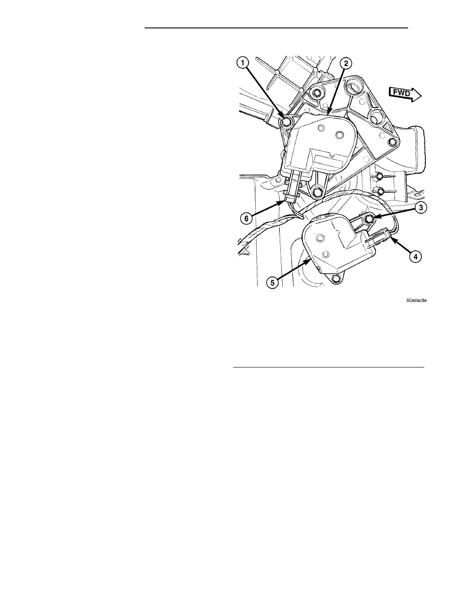
Fig. 10 Blend Door Actuator

1 - SCREW (2)
2 - MODE DOOR ACTUATOR
3 - SCREW (2)
4 - CONNECTOR
5 - BLEND DOOR ACTUATOR
6 - CONNECTOR

24 - 36

CONTROLS - REAR

RS

INFRARED TEMPERATURE SENSOR (Continued)

(7) Install and tighten the screw that secures the

back of the rear heater-A/C unit housing to the right
D-pillar. Tighten the screw to 11 N·m (97 in. lbs.).

(8) Install and tighten the two screws that secure

the top of the quarter trim panel attaching bracket to
the quarter inner panel. Tighten the screws to 1.7
N·m (15 in. lbs.).

(9) Reinstall the right quarter trim panel and

right D-pillar trim panel onto the quarter inner
panel. (Refer to 23 - BODY/INTERIOR/QUARTER
TRIM PANEL - INSTALLATION).

(10) Reconnect the battery negative cable.
(11) Perform the heater-A/C control calibration

procedure. (Refer to 24 - HEATING & AIR CONDI-
TIONING/CONTROLS - FRONT/A/C-HEATER CON-
TROL - STANDARD PROCEDURE - HEATER-A/C
CONTROL CALIBRATION).

POWER MODULE

DESCRIPTION

A blower power module is used on this model when

it is equipped with the optional Automatic Tempera-
ture Control (ATC) (Fig. 11). Models equipped with
the standard manual heater-A/C control use a blower
motor resistor, instead of the blower power module.

The blower power module is installed in a mounting
hole in the back of the rear heater-A/C unit housing,
directly above the expansion valve. The module con-
sists of a molded plastic mounting plate with two
integral connector receptacles. Concealed behind the
mounting plate within the evaporator housing is the
power module electronic circuitry and a large finned,
heat sink. The module mounting plate is secured
with two screws to the rear heater-A/C unit housing
and is accessed for service by removing the right
quarter and D-pillar trim panels.

The power module heat sink will get hot when in

use. Do not touch the heat sink if the blower motor
has been running. The blower power module cannot
be adjusted or repaired and, if faulty or damaged, it
must be replaced.

OPERATION

The blower power module is connected to the vehi-

cle electrical system through a dedicated take out
and connector of the rear HVAC wire harness. A sec-
ond connector receptacle receives the pigtail wire
connector from the blower motor. The blower power
module allows the microprocessor-based Automatic
Temperature Control (ATC) heater-A/C control mod-
ule to calculate and provide infinitely variable blower
motor speeds based upon either manual blower
switch input or the ATC programming using a Pulse
Width Modulated (PWM) circuit strategy. The PWM
voltage is applied to a comparator circuit which com-
pares the PWM signal voltage to the blower motor
feedback voltage. The resulting output drives the
power module circuitry, which adjusts the voltage
output received from the blower motor relay to
change or maintain the desired blower speed. The
blower power module is diagnosed using a DRBIII

t

scan tool. Refer to the appropriate diagnostic infor-
mation.

REMOVAL

(1) Disconnect and isolate the battery negative

cable.

(2) Remove the right quarter trim panel and right

D-pillar trim panel from the quarter inner panel.
(Refer to 23 - BODY/INTERIOR/QUARTER TRIM
PANEL - REMOVAL).

(3) Disconnect the rear HVAC wire harness con-

nector for the blower power module from the resistor
connector receptacle (Fig. 12).

(4) Disconnect the blower motor pigtail wire con-

nector from the blower power module connector
receptacle.

(5) Remove the two screws that secure the blower

power module to the rear heater-A/C unit housing.

(6) Remove the blower power module from the rear

heater-A/C unit housing.

Fig. 11 Power Module

1 - REAR HEATER-A/C UNIT HOUSING
2 - SCREW (2)
3 - D-PILLAR
4 - BLOWER PIGTAIL WIRE
5 - REAR HVAC WIRE HARNESS
6 - EXPANSION VALVE
7 - BLOWER POWER MODULE

RS

CONTROLS - REAR

24 - 37

MODE DOOR ACTUATOR (Continued)

INSTALLATION

(1) Position the blower power module into the rear

heater-A/C unit housing.

(2) Install and tighten the two screws that secure

the blower power module to the rear heater-A/C unit
housing. Tighten the screws to 2 N·m (17 in. lbs.).

(3) Reconnect the blower motor pigtail wire to the

blower power module connector receptacle.

(4) Reconnect the rear HVAC wire harness connec-

tor for the blower power module to the module con-
nector receptacle.

(5) Reinstall the right quarter trim panel and

right D-pillar trim panel onto the quarter inner
panel. (Refer to 23 - BODY/INTERIOR/QUARTER
TRIM PANEL - INSTALLATION).

(6) Reconnect the battery negative cable.

Fig. 12 Power Module

1 - REAR HEATER-A/C UNIT HOUSING
2 - SCREW (2)
3 - D-PILLAR
4 - BLOWER PIGTAIL WIRE
5 - REAR HVAC WIRE HARNESS
6 - EXPANSION VALVE
7 - BLOWER POWER MODULE

24 - 38

CONTROLS - REAR

RS

POWER MODULE (Continued)

DISTRIBUTION - FRONT

TABLE OF CONTENTS

page

page

AIR FILTER

DESCRIPTION

. . . . . . . . . . . . . . . . . . . . . . . . . 39

REMOVAL

. . . . . . . . . . . . . . . . . . . . . . . . . . . . . 39

INSTALLATION

. . . . . . . . . . . . . . . . . . . . . . . . . 40

AIR OUTLETS

DESCRIPTION

. . . . . . . . . . . . . . . . . . . . . . . . . 40

REMOVAL

REMOVAL - CENTER BEZEL OUTLETS

. . . . 40

REMOVAL - DEMISTER OUTLET

. . . . . . . . . . 41

REMOVAL - FRONT DOOR REAR OUTLET

. . 41

REMOVAL - INSTRUMENT PANEL OUTLET

. 42

INSTALLATION

INSTALLATION - CENTER BEZEL OUTLETS

. 42

INSTALLATION - DEMISTER OUTLET

. . . . . . 42

INSTALLATION - FRONT DOOR REAR

OUTLET . . . . . . . . . . . . . . . . . . . . . . . . . . . . 42

INSTALLATION - INSTRUMENT PANEL

OUTLET . . . . . . . . . . . . . . . . . . . . . . . . . . . . 42

BLOWER MOTOR

DESCRIPTION

. . . . . . . . . . . . . . . . . . . . . . . . . 43

OPERATION

. . . . . . . . . . . . . . . . . . . . . . . . . . . 43

DIAGNOSIS AND TESTING - BLOWER

MOTOR

. . . . . . . . . . . . . . . . . . . . . . . . . . . . . 43

REMOVAL

. . . . . . . . . . . . . . . . . . . . . . . . . . . . . 46

INSTALLATION

. . . . . . . . . . . . . . . . . . . . . . . . . 46

DEFROSTER DUCT

REMOVAL

. . . . . . . . . . . . . . . . . . . . . . . . . . . . . 47

INSTALLATION

. . . . . . . . . . . . . . . . . . . . . . . . . 48

DEMISTER DUCTS

REMOVAL

. . . . . . . . . . . . . . . . . . . . . . . . . . . . . 48

INSTALLATION

. . . . . . . . . . . . . . . . . . . . . . . . . 48

FLOOR DISTRIBUTION DUCTS

REMOVAL

. . . . . . . . . . . . . . . . . . . . . . . . . . . . . 48

INSTALLATION

. . . . . . . . . . . . . . . . . . . . . . . . . 49

HVAC HOUSING

REMOVAL

. . . . . . . . . . . . . . . . . . . . . . . . . . . . . 49

INSTALLATION

. . . . . . . . . . . . . . . . . . . . . . . . . 50

PANEL DUCTS

REMOVAL

. . . . . . . . . . . . . . . . . . . . . . . . . . . . . 51

INSTALLATION

. . . . . . . . . . . . . . . . . . . . . . . . . 51

AIR FILTER

DESCRIPTION

A dust and odor air filter is standard equipment on

models equipped with the three zone temperature
control systems (Fig. 1). The filter element is the
same size as the front air conditioner evaporator to
ensure ample filtering capacity. A removable door on
the bottom of the front heater-A/C unit housing
below the glove box provides easy access to the filter
element for replacement. Filter replacement is rec-
ommended at 24,000 kilometer (15,000 mile) inter-
vals.

REMOVAL

(1) Locate the air filter door on the bottom of the

lower evaporator housing just outboard of the pas-
senger side of the instrument panel center stack (Fig.
2).

(2) Slide the air filter door latch toward the rear of

the vehicle until it engages the opened stop on the
door.

(3) Pull the air filter door straight downward to

disengage it from the air filter opening of the lower
evaporator housing.

(4) Use your fingers to reach through the air filter

opening of the lower evaporator housing far enough
to grasp the air filter.

(5) Pull the air filter straight down and out of the

evaporator housing (Fig. 2).

Fig. 1 Air Filter

1 - LOWER EVAPORATOR HOUSING
2 - LOWER EDGE OF INSTRUMENT PANEL
3 - AIR FILTER
4 - INSTRUMENT PANEL CENTER FLOOR BRACKET COVER
5 - FILTER SEALING EDGES
6 - AIR FILTER OPENING (IF EQUIPPED)

RS

DISTRIBUTION - FRONT

24 - 39


Content   ..  507  508  509  510   ..