Chrysler Town, Dodge Caravan. Manual - part 436


  Index      Chrysler     Chrysler TOWN & COUNTRY, VOYAGER, Dodge Caravan - service repair manual 2001-2007 year


Search            


Content   ..  434  435  436  437   ..


Chrysler Town, Dodge Caravan. Manual - part 436


(1) Cover waxed paper or plastic with adhesive

backed nylon mesh (dry wall tape) larger than the
patch required (Fig. 8).

(2) Tape waxed paper or plastic sheet with mesh to

a surface that has a compatible contour to the repair
area.

(3) Apply a liberal coat of adhesive over the rein-

forcement mesh (Fig. 8). If necessary apply a second
or third coat of adhesive and mesh after firs coat has
cured. The thickness of the patch should be the same
as the repair area.

(4) After patch has cured, peel waxed paper or

plastic from the back of the patch.

(5) If desired, a thin film coat of adhesive can be

applied to the back of the patch to cover mesh for
added strength.

PANEL PATCH INSTALLATION

(1) Make a paper or cardboard pattern the size

and shape of the cutout hole in the panel.

(2) Trim 3 mm (0.125 in.) from edges of pattern so

patch will have a gap between connecting surfaces.

(3) Using the pattern as a guide, cut the patch to

size.

(4) Cut scrap pieces of patch material into 50 mm

(2 in.) squares to use as patch supports to sustain
the patch in the cutout.

(5) Drill 4 mm (0.160 in.) holes 13 mm (0.5 in.) in

from edge of cutout hole (Fig. 7).

(6) Drill 4 mm (0.160 in.) holes 13 mm (0.5 in.)

away from edge of patch across from holes drilled
around cutout.

(7) Drill 3 mm (0.125 in.) holes in the support

squares 13 mm (0.5 in.) from the edge in the center
of one side.

(8) Scuff the backside of the body panel around the

cutout hole with a scuff pad or sandpaper.

(9) Mix enough adhesive to cover one side of all

support squares.

(10) Apply adhesive to cover one side of all support

squares.

(11) Using number 8 sheet metal screws, secure

support squares to back side of body panel with
adhesive sandwiched between the panel and squares
(Fig. 9).

(12) Position patch in cutout against support

squares and adjust patch until the gap is equal along
all sides (Fig. 10).

(13) Drill 3 mm (0.125 in.) holes in the support

squares through the pre-drilled holes in the patch.

(14) Apply a coat of adhesive to the exposed ends

of the support squares (Fig. 11).

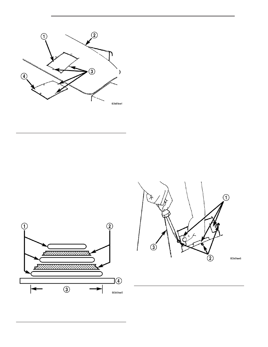
Fig. 7 DAMAGED PANEL CUTOUT AND PATCH

1 - CUTOUT
2 - DAMAGED BODY PANEL
3 - 4 MM (0.160 IN.) HOLES
4 - PATCH CUT TO SIZE

Fig. 8 FABRICATED PANEL

1 - STRUCTURAL ADHESIVE
2 - FIBERGLASS CLOTH OR FIBERGLASS MESH TAPE
3 - WIDTH OF V-GROOVE
4 - WAXED PAPER

Fig. 9 SECURE SUPPORT SQUARES TO BODY PANEL

1 - SUPPORT SQUARES
2 - SCREWS
3 - DAMAGED BODY PANEL

23 - 8

BODY

RS

BODY (Continued)

(15) Install screws to hold the patch to support

squares (Fig. 12). Tighten screws until patch surface
is flush with panel surface.

(16) Allow adhesive to cure, and remove all screws.
(17) Using a 125 mm (5 in.) 24 grit disc grinder,

grind a 50 mm (2 in.) to 75 mm (3 in.) wide and 2
mm (0.080 in.) deep path across the gaps around the
patch (Fig. 13). With compressed air, blow dust from
around patch.

(18) Apply adhesive backed nylon mesh (dry wall

tape) over gaps around patch (Fig. 14).

(19) Mix enough adhesive to cover the entire patch

area.

(20) Apply adhesive over the mesh around patch,

and smooth epoxy with a wide spreader to reduce fin-
ish grinding. Use two to three layers of mesh and
adhesive to create a stronger repair (Fig. 15).

PATCHED PANEL SURFACING

After patch panel is installed, the patch area can

be finished using the same methods as finishing
other types of body panels. If mesh material is
exposed in the patched area, grind surface down, and
apply a coat of high quality rigid plastic body filler.
Prime, block sand, and paint as required.

Fig. 10 POSITION PATCH IN CUTOUT AND ALIGN

1 - CUTOUT
2 - SUPPORT SQUARES

Fig. 11 APPLY ADHESIVE TO SUPPORT SQUARES

1 - APPLICATOR
2 - SUPPORT SQUARES
3 - ADHESIVE

Fig. 12 INSTALL SCREWS

1 - PATCH
2 - GAP

Fig. 13 GRIND SURFACE

1 - PATCH
2 - GAP
3 - DISC GRINDER

RS

BODY

23 - 9

BODY (Continued)

STANDARD PROCEDURE - HEAT STAKING

(1) Remove trim panel.
(2) Bend or move the trim panel components at

the heat staked joints. Observe the heat staked loca-
tions and/or component seams for looseness.

(3) Heat stake the components.

(a) If the heat staked or component seam loca-

tion is loose, hold the two components tightly
together and using a soldering gun with a flat tip,
melt

the

material

securing

the

components

together. Do not over heat the affected area, dam-
age to the exterior of the trim panel may occur.

(b) If the heat staked material is broken or miss-

ing, use a hot glue gun to apply new material to
the area to be repaired. The panels that are being
heat staked must be held together while the apply-
ing the glue. Once the new material is in place, it
may be necessary to use a soldering gun to melt
the newly applied material. Do not over heat the
affected area, damage to the exterior of the trim
panel may occur.
(4) Allow the repaired area to cool and verify the

repair.

(5) Install trim panel.

Fig. 14 COVER GAPS WITH MESH

1 - GROUND DOWN AREA
2 - PATCH
3 - MESH

Fig. 15 COVER MESH WITH ADHESIVE

1 - ADHESIVE
2 - MESH
3 - PATCH
4 - SPREADER

23 - 10

BODY

RS

BODY (Continued)

SPECIFICATIONS

TORQUE

TORQUE SPECIFICATIONS

DESCRIPTION

N·m

Ft. Lbs.

In. Lbs.

All seat belt anchor bolts

39

29

Armrest shoulder bolt

29

21

Bench seat riser bolts

48

35

Bench seat track nuts

48

35

Quad bucket seat track to cushion frame bolts

40

30

Bucket seat back pivot bolts

33

24

Center seat to seat track bolts

24

17

Child seat module screws (bench seats)

7

62

Child seat module screws (quad seats)

13.5

10

Crossmember to radiator closure panel bolts

28

21

Door check strap to door end frame

12

105

Door latch to door end frame bolts

10

89

Floor latch to seat cushion frame bolts

27

19

Front cover to seat track screws

4

32

Front door hinge to hinge pillar bolts

34

25

Front door hinge to door nuts and bolts

34

25

Front door latch striker bolts

28

21

Front/quad seat cushion bolts

28.5

21

Front seat belt retractor bolts

38

28

Front seat riser to floor nuts

60

44

Front seat track cover screws

4

35

Front seat riser to seat track nuts

81

60

Front seatback pivot bolts

54

40

Front seatback recliner nut

12

105

Front seatback assist strap screws

2.5

22

Grocery bag holder screws

2

17

Hinge to liftgate bolts

33

24

Hood latch to bolts

13.5

10

Hood latch striker bolts

13.5

10

Hood hinge to hood bolts

13.5

10

Liftgate exterior handle outer screws

20

15

Liftgate exterior handle inner bolts

40

30

Lifgate hinge to roof header bolts

33

24

Liftgate latch bolts

16

12

Liftgate latch striker bolts

28

21

Liftgate lift motor link to liftgate

28

21

Liftgate spoiler bolts

9

80

Lifgate stabilizer wedge striker to D-pillar bolts

3

30

RS

BODY

23 - 11

BODY (Continued)


Content   ..  434  435  436  437   ..