Chrysler Town, Dodge Caravan. Manual - part 434


  Index      Chrysler     Chrysler TOWN & COUNTRY, VOYAGER, Dodge Caravan - service repair manual 2001-2007 year


Search            


Content   ..  432  433  434  435   ..


Chrysler Town, Dodge Caravan. Manual - part 434


INSTALLATION

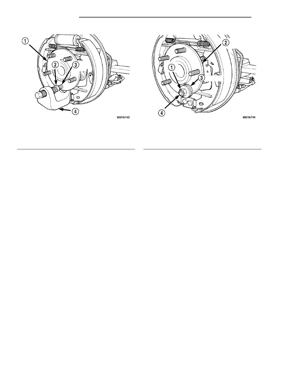
(1) Install replacement wheel stud into flange of

hub and bearing assembly. Install washers on wheel
stud, then install a wheel lug nut on stud with flat
side of lug nut against washers (Fig. 38).

(2) Tighten the wheel lug nut, pulling the wheel

stud into the flange of the hub and bearing assembly.
When the head of the stud is fully seated against the
bearing flange, remove lug nut and washers from
wheel stud.

(3) Install the brake drum or disc brake rotor and

caliper on the hub and bearing assembly.

(4) Install wheel and tire assembly on vehicle.

Tighten the wheel mounting stud nuts in proper
sequence until all nuts are torqued to half specifica-
tion. Then repeat the tightening sequence to the full
specified torque of 135 N·m (100 ft. lbs.).

(5) Lower vehicle to the ground.

Fig. 37 Wheel Stud Removal From Hub And Bearing

1 - HUB AND BEARING ASSEMBLY
2 - WHEEL MOUNTING (LUG) NUT
3 - WHEEL STUD
4 - SPECIAL TOOL C-4150A

Fig. 38 Wheel Stud Installation

1 - WHEEL MOUNTING (LUG) NUT
2 - HUB AND BEARING ASSEMBLY
3 - WASHERS
4 - WHEEL STUD

22 - 22

TIRES/WHEELS

RS

WHEEL MOUNTING STUDS - REAR (Continued)

BODY

TABLE OF CONTENTS

page

page

BODY

DESCRIPTION - VEHICLE IDENTIFICATION

. . . . 1

WARNING

SAFETY PRECAUTIONS AND WARNINGS

. . . 1

DIAGNOSIS AND TESTING

DIAGNOSIS AND TESTING - WATER LEAKS

. 2

DIAGNOSIS AND TESTING - WIND NOISE

. . . 3

STANDARD PROCEDURE

STANDARD PROCEDURE - PLASTIC BODY

PANEL REPAIR . . . . . . . . . . . . . . . . . . . . . . . . 3

STANDARD PROCEDURE - HEAT STAKING

. 10

SPECIFICATIONS

TORQUE

. . . . . . . . . . . . . . . . . . . . . . . . . . . . 11

BODY LUBRICATION

. . . . . . . . . . . . . . . . . . . 12

SPECIAL TOOLS

BODY

. . . . . . . . . . . . . . . . . . . . . . . . . . . . . . 13

DOOR - FRONT

. . . . . . . . . . . . . . . . . . . . . . . . . 14

DOORS - SLIDING

. . . . . . . . . . . . . . . . . . . . . . . 24

DECKLID/HATCH/LIFTGATE/TAILGATE

. . . . . . . 39

EXTERIOR

. . . . . . . . . . . . . . . . . . . . . . . . . . . . . 44

HOOD

. . . . . . . . . . . . . . . . . . . . . . . . . . . . . . . . . 59

INSTRUMENT PANEL

. . . . . . . . . . . . . . . . . . . . . 62

INTERIOR

. . . . . . . . . . . . . . . . . . . . . . . . . . . . . . 72

PAINT

. . . . . . . . . . . . . . . . . . . . . . . . . . . . . . . . . 83

SEATS

. . . . . . . . . . . . . . . . . . . . . . . . . . . . . . . . 85

STATIONARY GLASS

. . . . . . . . . . . . . . . . . . . . 105

WEATHERSTRIP/SEALS

. . . . . . . . . . . . . . . . . . 110

SUNROOF

. . . . . . . . . . . . . . . . . . . . . . . . . . . . . 113

BODY STRUCTURE

. . . . . . . . . . . . . . . . . . . . . 121

BODY

DESCRIPTION - VEHICLE IDENTIFICATION

Throughout

this

group,

references

to

the

DaimlerChrysler Corporation vehicle family identifi-
cation code are used when describing a procedure
that is unique to that vehicle. Refer to Introduction
Group of this manual for detailed information on
vehicle identification. If a procedure is common to all
vehicles covered in this manual, no reference will be
made to a vehicle family code.

WARNING

SAFETY PRECAUTIONS AND WARNINGS

WARNING: USE A OSHA APPROVED BREATHING
FILTER WHEN SPRAYING PAINT OR SOLVENTS IN
A

CONFINED

AREA.

PERSONAL

INJURY

CAN

RESULT.
AVOID PROLONGED SKIN CONTACT WITH PETRO-
LEUM OR ALCOHOL – BASED CLEANING SOL-
VENTS. PERSONAL INJURY CAN RESULT.
DO NOT STAND UNDER A HOISTED VEHICLE THAT

IS

NOT

PROPERLY

SUPPORTED

ON

SAFETY

STANDS. PERSONAL INJURY CAN RESULT.

CAUTION: When holes must be drilled or punched
in an inner body panel, verify depth of space to the
outer body panel, electrical wiring, or other compo-
nents. Damage to vehicle can result.
Do not weld exterior panels unless combustible
material on the interior of vehicle is removed from
the repair area. Fire or hazardous conditions, can
result.
Always have a fire extinguisher ready for use when
welding.
Disconnect the negative (-) cable clamp from the
battery when servicing electrical components that
are live when the ignition is OFF. Damage to electri-
cal system can result.
Do not use abrasive chemicals or compounds on
painted surfaces. Damage to finish can result.
Do not use harsh alkaline based cleaning solvents
on painted or upholstered surfaces. Damage to fin-
ish or color can result.
Do not hammer or pound on plastic trim panel
when servicing interior trim. Plastic panels can
break.

RS

BODY

23 - 1

DIAGNOSIS AND TESTING

DIAGNOSIS AND TESTING - WATER LEAKS

Water leaks can be caused by poor sealing,

improper body component alignment, body seam
porosity, missing plugs, or blocked drain holes. Cen-
trifugal and gravitational force can cause water to
drip from a location away from the actual leak point,
making leak detection difficult. All body sealing
points should be water tight in normal wet-driving
conditions. Water flowing downward from the front of
the vehicle should not enter the passenger or luggage
compartment.

Moving

sealing

surfaces

will

not

always seal water tight under all conditions. At
times, side glass or door seals will allow water to
enter the passenger compartment during high pres-
sure washing or hard driving rain (severe) condi-
tions.

Overcompensating

on

door

or

glass

adjustments to stop a water leak that occurs under
severe conditions can cause premature seal wear and
excessive closing or latching effort. After completing
a repair, water test vehicle to verify leak has stopped
before returning vehicle to use.

VISUAL INSPECTION BEFORE WATER LEAK TESTS

Verify that floor and body plugs are in place, body

drains are clear, and body components are properly
aligned and sealed. If component alignment or seal-
ing is necessary, refer to the appropriate section of
this group for proper procedures.

WATER LEAK TESTS

WARNING: DO NOT USE ELECTRIC SHOP LIGHTS
OR TOOLS IN WATER TEST AREA. PERSONAL
INJURY CAN RESULT.

When the conditions causing a water leak have

been determined, simulate the conditions as closely
as possible.

• If a leak occurs with the vehicle parked in a

steady light rain, flood the leak area with an open-
ended garden hose.

• If a leak occurs while driving at highway speeds

in a steady rain, test the leak area with a reasonable
velocity stream or fan spray of water. Direct the
spray in a direction comparable to actual conditions.

• If a leak occurs when the vehicle is parked on an

incline, hoist the end or side of the vehicle to simu-
late this condition. This method can be used when
the leak occurs when the vehicle accelerates, stops or
turns. If the leak occurs on acceleration, hoist the
front of the vehicle. If the leak occurs when braking,
hoist the back of the vehicle. If the leak occurs on left
turns, hoist the left side of the vehicle. If the leak
occurs on right turns, hoist the right side of the vehi-

cle. For hoisting recommendations (Refer to LUBRI-
CATION

&

MAINTENANCE/HOISTING

-

STANDARD PROCEDURE).

WATER LEAK DETECTION

To detect a water leak point-of-entry, do a water

test and watch for water tracks or droplets forming
on the inside of the vehicle. If necessary, remove inte-
rior trim covers or panels to gain visual access to the
leak area. If the hose cannot be positioned without
being held, have someone help do the water test.

Some water leaks must be tested for a considerable

length of time to become apparent. When a leak
appears, find the highest point of the water track or
drop. The highest point usually will show the point of
entry. After leak point has been found, repair the
leak and water test to verify that the leak has
stopped.

Locating the entry point of water that is leaking

into a cavity between panels can be difficult. The
trapped water may splash or run from the cavity,
often at a distance from the entry point. Most water
leaks of this type become apparent after accelerating,
stopping, turning, or when on an incline.

MIRROR INSPECTION METHOD

When a leak point area is visually obstructed, use

a suitable mirror to gain visual access. A mirror can
also be used to deflect light to a limited-access area
to assist in locating a leak point.

BRIGHT LIGHT LEAK TEST METHOD

Some water leaks in the luggage compartment can

be detected without water testing. Position the vehicle
in a brightly lit area. From inside the darkened lug-
gage compartment inspect around seals and body
seams. If necessary, have a helper direct a drop light
over the suspected leak areas around the luggage com-
partment. If light is visible through a normally sealed
location, water could enter through the opening.

PRESSURIZED LEAK TEST METHOD

When a water leak into the passenger compart-

ment cannot be detected by water testing, pressurize
the passenger compartment and soap test exterior of
the vehicle. To pressurize the passenger compart-
ment, close all doors and windows, start engine, and
set heater control to high blower in HEAT position. If
engine can not be started, connect a charger to the
battery to ensure adequate voltage to the blower.
With interior pressurized, apply dish detergent solu-
tion to suspected leak area on the exterior of the
vehicle. Apply detergent solution with spray device or
soft bristle brush. If soap bubbles occur at a body
seam, joint, seal or gasket, the leak entry point could
be at that location.

23 - 2

BODY

RS

BODY (Continued)

DIAGNOSIS AND TESTING - WIND NOISE

Wind noise is the result of most air leaks. Air leaks

can be caused by poor sealing, improper body compo-
nent alignment, body seam porosity, or missing plugs
in the engine compartment or door hinge pillar areas.
All body sealing points should be airtight in normal
driving conditions. Moving sealing surfaces will not
always seal airtight under all conditions. At times,
side glass or door seals will allow wind noise to be
noticed in the passenger compartment during high
cross winds. Over compensating on door or glass
adjustments to stop wind noise that occurs under
severe conditions can cause premature seal wear and
excessive closing or latching effort. After a repair pro-
cedure has been performed, test vehicle to verify
noise has stopped before returning vehicle to use.

VISUAL INSPECTION BEFORE TESTS

Verify that floor and body plugs are in place and

body components are aligned and sealed. If compo-
nent alignment or sealing is necessary, refer to the
appropriate section of this group for proper proce-
dures.

ROAD TESTING WIND NOISE

(1) Drive the vehicle to verify the general location

of the wind noise.

(2) Apply 50 mm (2 in.) masking tape in 150 mm

(6 in.) lengths along weatherstrips, weld seams or
moldings. After each length is applied, drive the vehi-
cle. If noise goes away after a piece of tape is applied,
remove tape, locate, and repair defect.

POSSIBLE CAUSE OF WIND NOISE

• Moldings standing away from body surface can

catch wind and whistle.

• Gaps in sealed areas behind overhanging body

flanges can cause wind-rushing sounds.

• Misaligned movable components.

• Missing or improperly installed plugs in pillars.

• Weld burn through holes.

STANDARD PROCEDURE

STANDARD PROCEDURE - PLASTIC BODY
PANEL REPAIR

There are many different types of plastics used in

today’s automotive environment. We group plastics in
three different categories: Rigid, Semi-Rigid, and
Flexible. Any of these plastics may require the use of
an adhesion promoter for repair. These types of plas-
tic are used extensively on DaimlerChrysler Motors
vehicles. Always follow repair material manufactur-
er’s plastic identification and repair procedures.

Rigid Plastics:

Examples of rigid plastic use: Fascias, Hoods,

Doors, and other Body Panels, which include SMC,
ABS, and Polycarbonates.

Semi-Rigid Plastics:

Examples of semi-rigid plastic use: Interior Panels,

Under Hood Panels, and other Body Trim Panels.

Flexible Plastics:

Examples of flexible plastic use: Fascias, Body

Moldings, and upper and lower Fascia Covers.

Repair Procedure:

The repair procedure for all three categories of

plastics is basically the same. The one difference is
the material used for the repair. The materials must
be specific for each substrate, rigid repair material
for rigid plastic repair, semi-rigid repair material for
semi-rigid plastic repair and flexible repair material
for flexible plastic repair.

Adhesion Promoter/Surface Modifier:

Adhesion Promoters/Surface Modifiers are required

for certain plastics. All three categories may have
plastics that require the use of adhesion promoter/
surface modifiers. Always follow repair material man-
ufacturer’s

plastic

identification

and

repair

procedures.

SAFETY PRECAUTION AND WARNINGS

WARNING:

EYE PROTECTION SHOULD BE USED WHEN

SERVICING

COMPONENTS.

PERSONAL

INJURY

CAN RESULT.

USE AN OSHA APPROVED BREATHING MASK

WHEN MIXING EPOXY, GRINDING, AND SPRAYING
PAINT OR SOLVENTS IN A CONFINED AREA. PER-
SONAL INJURY CAN RESULT.

AVOID PROLONGED SKIN CONTACT WITH

RESIN, PETROLEUM, OR ALCOHOL BASED SOL-
VENTS. PERSONAL INJURY CAN RESULT.

DO NOT VENTURE UNDER A HOISTED VEHI-

CLE THAT IS NOT PROPERLY SUPPORTED ON
SAFETY

STANDS.

PERSONAL

INJURY

CAN

RESULT.

NOTE:

When holes must be drilled or cut in body pan-

els, verify locations of internal body components
and electrical wiring. Damage to vehicle can result.

Do not use abrasive chemicals or compounds

on undamaged painted surfaces around repair
areas. Damage to finish can result.

RS

BODY

23 - 3

BODY (Continued)


Content   ..  432  433  434  435   ..