Chrysler Town, Dodge Caravan. Manual - part 419


  Index      Chrysler     Chrysler TOWN & COUNTRY, VOYAGER, Dodge Caravan - service repair manual 2001-2007 year


Search            


Content   ..  417  418  419  420   ..


Chrysler Town, Dodge Caravan. Manual - part 419


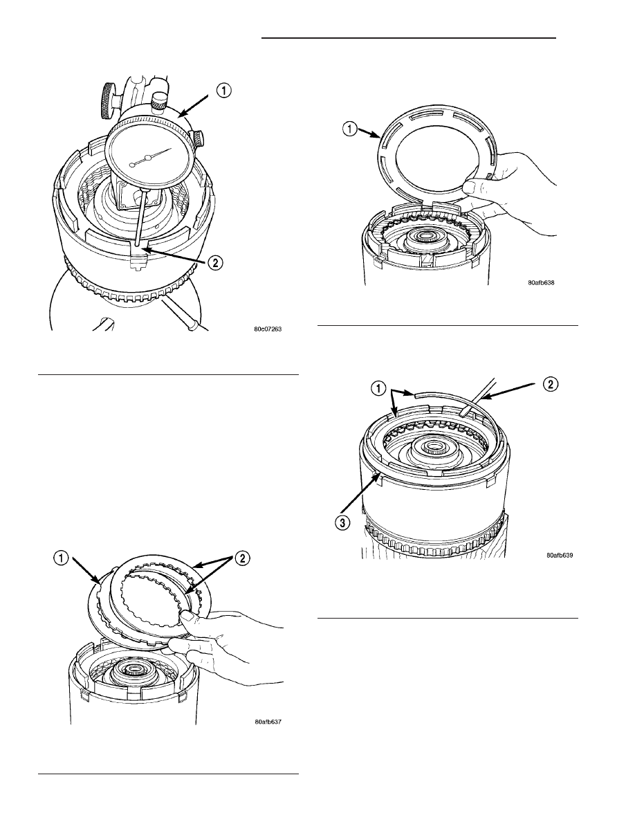
(26) Zero dial indicator and apply 30 psi (206 kPa)

air pressure to the overdrive clutch hose on Tool
8391. Measure and record OD clutch pack measure-
ment in four (4) places, 90° apart.

(27) Take average of four measurements and com-

pare with OD clutch pack clearance specification.
The overdrive (OD) clutch pack clearance is
1.07-3.25 mm (0.042-0.128 in.).

If not within specifications, the clutch is not

assembled properly. There is no adjustment for the
OD clutch clearance.

(28) Install reverse clutch pack (two frictions/one

steel) (Fig. 270).

(29) Install reverse clutch reaction plate with the

flat side down towards reverse clutch (Fig. 271).

(30) Tap reaction plate down to allow installation

of the reverse clutch snap ring. Install reverse clutch
snap ring (Fig. 272) (Fig. 273).

(31) Pry up reverse reaction plate to seat against

snap ring (Fig. 274).

(32) Set up a dial indicator on the reverse clutch

pack as shown in (Fig. 275).

Fig. 269 Measure OD Clutch Pack Clearance

1 - DIAL INDICATOR
2 - OD/REVERSE REACTION PLATE

Fig. 270 Install Reverse Clutch Pack

1 - REVERSE CLUTCH PLATE
2 - REVERSE CLUTCH DISCS

Fig. 271 Install Reaction Plate

1 - REVERSE CLUTCH REACTION PLATE (FLAT SIDE DOWN)

Fig. 272 Install Reverse Clutch Snap Ring

1 - REVERSE CLUTCH SNAP RING (SELECT)
2 - SCREWDRIVER
3 - REVERSE CLUTCH REACTION PLATE

21 - 226

41TE AUTOMATIC TRANSAXLE

RS

INPUT CLUTCH ASSEMBLY (Continued)

Fig. 273 Reverse Clutch Assembly

1 - SNAP RING
2 - REACTION PLATE
3 - CLUTCH DISC (2)

4 - CLUTCH PLATE (1)
5 - INPUT CLUTCH ASSEMBLY

Fig. 274 Pry Up Reaction Plate to Seat Against Snap

Ring

1 - SCREWDRIVER
2 - SNAP RING
3 - SCREWDRIVER
4 - MUST RAISE REVERSE REACTION PLATE TO RAISE SNAP
RING

Fig. 275 Measure Reverse Clutch Pack Clearance

1 - DIAL INDICATOR
2 - REVERSE CLUTCH

RS

41TE AUTOMATIC TRANSAXLE

21 - 227

INPUT CLUTCH ASSEMBLY (Continued)

(33) Using moderate pressure, press down and

hold (near indicator) reverse clutch disc with screw-
driver or suitable tool and zero dial indicator (Fig.
276). When releasing pressure, indicator should
advance 0.005-0.010. as clutch pack relaxes.

(34) Apply 30 psi (206 kPa) air pressure to the

reverse clutch hose on Tool 8391. Measure and record
reverse clutch pack measurement in four (4) places,
90° apart.

(35) Take average of four measurements and com-

pare with reverse clutch pack clearance specification.
The reverse clutch pack clearance is 0.89-1.37
mm (0.035-0.054 in.). 
Select the proper reverse
clutch snap ring to achieve specifications:

REVERSE CLUTCH SNAP RING THICKNESS

4377195

1.53-1.58 mm (0.060-0.062 in.)

4412871

1.77-1.83 mm (0.070-0.072 in.)

4412872

2.02-2.07 mm (0.080-0.082 in.)

4412873

2.27-2.32 mm (0.090-0.091 in.)

(36) To complete the assembly, reverse clutch and

overdrive clutch must be removed.

(37) Install the #2 needle bearing (Fig. 277).

(38) Install the underdrive shaft assembly (Fig.

278).

Fig. 276 Press Down on Reverse Clutch and Zero

Indicator

1 - DIAL INDICATOR
2 - REVERSE CLUTCH

Fig. 277 Install No. 2 Needle Bearing

1 - #2 NEEDLE BEARING (NOTE 3 SMALL TABS)
2 - TABS UP

Fig. 278 Install Underdrive Shaft Assembly

1 - UNDERDRIVE SHAFT ASSEMBLY
2 - #2 NEEDLE BEARING

21 - 228

41TE AUTOMATIC TRANSAXLE

RS

INPUT CLUTCH ASSEMBLY (Continued)

(39) Install the #3 thrust washer to the underdrive

shaft assembly. Be sure five tabs are seated properly
(Fig. 279).

(40) Install the #3 thrust plate to the bottom of the

overdrive shaft assembly. Retain with petrolatum or
transmission assembly gel (Fig. 280).

(41) Install the overdrive shaft assembly (Fig. 281)

(Fig. 282).

(42) Reinstall overdrive and reverse clutch as

shown. Rechecking these clutch clearances is
not necessary.

Fig. 279 Install No. 3 Thrust Washer

1 - #3 THRUST WASHER (NOTE 5 TABS)
2 - UNDERDRIVE SHAFT ASSEMBLY

Fig. 280 Install No. 3 Thrust Plate

1 - OVERDRIVE SHAFT ASSEMBLY
2 - DABS OF PETROLATUM (FOR RETENTION)
3 - #3 THRUST PLATE (NOTE 3 TABS)

Fig. 281 Install Overdrive Shaft Assembly

1 - OVERDRIVE SHAFT ASSEMBLY
2 - #3 THRUST PLATE
3 - #3 THRUST WASHER

RS

41TE AUTOMATIC TRANSAXLE

21 - 229

INPUT CLUTCH ASSEMBLY (Continued)


Content   ..  417  418  419  420   ..