Chrysler Town, Dodge Caravan. Manual - part 418


  Index      Chrysler     Chrysler TOWN & COUNTRY, VOYAGER, Dodge Caravan - service repair manual 2001-2007 year


Search            


Content   ..  416  417  418  419   ..


Chrysler Town, Dodge Caravan. Manual - part 418


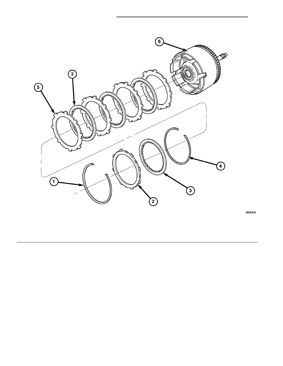
Fig. 260 Underdrive Clutch Assembly

1 - SNAP RING (TAPERED)
2 - OD/UD REACTION PLATE
3 - CLUTCH DISC

4 - SNAP RING (FLAT)
5 - CLUTCH PLATE
6 - INPUT CLUTCH ASSEMBLY

21 - 222

41TE AUTOMATIC TRANSAXLE

RS

INPUT CLUTCH ASSEMBLY (Continued)

(15) Install input clutch assembly to the Input

Clutch Pressure Fixture–Tool 8391 (Fig. 261).

(16) Set up dial indicator on the UD clutch pack as

shown in (Fig. 262).

(17) Using moderate pressure, press down and

hold (near indicator) the UD clutch pack with screw-
driver or suitable tool and zero dial indicator (Fig.
263). When releasing pressure on clutch pack, indica-
tor reading should advance 0.005–0.010.

CAUTION: Do not apply more than 30 psi (206 kPa)
to the underdrive clutch pack.

(18) Apply 30 psi (206 kPa) to the underdrive hose

on Tool 8391 and measure UD clutch clearance. Mea-
sure and record UD clutch pack measurement in four
(4) places, 90° apart.

(19) Take average of four measurements and com-

pare with UD clutch pack clearance specification.
Underdrive clutch pack clearance must be 0.94-
1.50 mm (0.037-0.059 in.).

(20) If necessary, select the proper reaction plate

to achieve specifications:

UNDERDRIVE REACTION PLATE THICKNESS

4659939AB

5.837-5.937 mm (0.230-0.234 in.)

4659940AB

6.147-6.248 mm (0.242-0.246 in.)

4659941AB

6.457-6.557 mm (0.254-0.258 in.)

Fig. 261 Input Clutch Assembly on Pressure Fixture

Tool 8391

1 - INPUT CLUTCH ASSEMBLY
2 - INPUT CLUTCH PRESSURE FIXTURE 8391

Fig. 262 Set Up Dial Indicator to Measure UD Clutch

Clearance

1 - DIAL INDICATOR
2 - UNDERDRIVE CLUTCH

Fig. 263 Press Down on UD Clutch Pack and Zero

Dial Indicator

1 - DIAL INDICATOR
2 - UNDERDRIVE CLUTCH

RS

41TE AUTOMATIC TRANSAXLE

21 - 223

INPUT CLUTCH ASSEMBLY (Continued)

(21) Install the OD clutch pack (four frictions/three

steels) (Fig. 264).

(22) Install OD pressure plate waved snap ring

(Fig. 265).

(23) Install the OD/Reverse pressure plate with

large step down (towards OD clutch pack) (Fig. 266).

(24) Install OD pressure plate flat snap ring (Fig.

267) (Fig. 268).

Fig. 264 Install OD Clutch Pack

1 - OVERDRIVE CLUTCH PACK

Fig. 265 Install Waved Snap Ring

1 - OVERDRIVE PRESSURE PLATE WAVED SNAP RING
2 - SCREWDRIVER

Fig. 266 OD/Reverse Pressure Plate

1 - OVERDRIVE/REVERSE PRESSURE PLATE
2 - (STEP SIDE DOWN)

Fig. 267 Install Flat Snap Ring

1 - ARBOR PRESS RAM
2 - TOOL 5059A
3 - FLAT SNAP RING

21 - 224

41TE AUTOMATIC TRANSAXLE

RS

INPUT CLUTCH ASSEMBLY (Continued)

(25) Measure OD clutch pack clearance. Set up

dial indicator on top of the OD/Reverse pressure
plate as shown in (Fig. 269).

Fig. 268 Overdrive Clutch Assembly

1 - SNAP RING
2 - OD/REVERSE PRESSURE PLATE
3 - SNAP RING (WAVE)

4 - CLUTCH DISC (4)
5 - CLUTCH STEEL (3)
6 - INPUT CLUTCH ASSEMBLY

RS

41TE AUTOMATIC TRANSAXLE

21 - 225

INPUT CLUTCH ASSEMBLY (Continued)


Content   ..  416  417  418  419   ..