Chrysler Town, Dodge Caravan. Manual - part 378


  Index      Chrysler     Chrysler TOWN & COUNTRY, VOYAGER, Dodge Caravan - service repair manual 2001-2007 year


Search            


Content   ..  376  377  378  379   ..


Chrysler Town, Dodge Caravan. Manual - part 378


BACK-UP LAMP SWITCH

REMOVAL

(1) Raise vehicle on hoist.
(2) Disconnect back-up lamp switch connector.
(3) Remove back-up lamp switch (Fig. 95).

INSTALLATION

(1) Install back-up lamp switch (Fig. 95) and

torque to 23 N·m (17 ft. lbs.) using Tool 8827.

(2) Connect back-up lamp switch connector.
(3) Lower vehicle.

DIFFERENTIAL

DESCRIPTION

The T850 differential is a conventional open design.

It consists of a ring gear and a two-piece differential
case. The differential case contains the pinion and side
gears, three floating pinion shafts, and a pinion shaft
retaining ring (Fig. 96). The differential case is sup-
ported in the transaxle by tapered roller bearings.

OPERATION

The differential assembly is driven by the interme-

diate shaft via the ring gear. The ring gear drives the
differential case, and the case drives the halfshafts
through the differential gears. The differential pinion
and side gears are supported in the case by pinion
shafts and thrust washers. Differential pinion and
side gears make it possible for front wheels to rotate
at different speeds while cornering.

DISASSEMBLY

(1) Remove differential side bearings:

(a) Install button 8491-1 to differential case (Fig.

97).

(b) Set up Tool 5048 (5048-1, -4, -6) as shown in

(Fig. 98).

(c) Remove differential side bearing (Fig. 99).

Same procedure/tools work for both sides.

Fig. 95 Back-Up Lamp Switch

1 - BACK-UP LAMP SWITCH

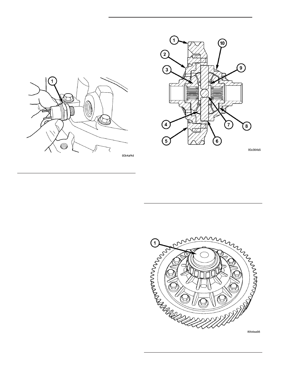
Fig. 96 Differential Assembly

1 - RING GEAR
2 - SUPPORT PLATE
3 - SIDE GEAR (2)
4 - PINION GEAR (4)
5 - BOLT (12)
6 - PINION SHAFT (2-SHORT)
7 - PINION SHAFT (1-LONG)
8 - THRUST WASHER (2)
9 - RETAINING RING
10 - DIFFERENTIAL CASE

Fig. 97 Tool 8491

1 - TOOL 8491

21 - 62

T850 MANUAL TRANSAXLE

RS

(2) Remove ring gear-to-case bolts (Fig. 100) and

remove ring gear.

(3) Using three ring gear bolts as forcing screws

(Fig. 101), separate differential support from case
(Fig. 102).

Fig. 98 Puller 5048

1 - 5048-1 FORCING SCREW
2 - 5048-4 COLLETS
3 - 5048-6 SLEEVE

Fig. 99 Differential Side Bearing Removal

1 - TOOL 5048

Fig. 100 Ring Gear-to-Differential Case Bolts

1 - BOLT (12)
2 - DIFFERENTIAL SUPPORT
3 - RING GEAR

Fig. 101 Separate Differential Case Halves

1 - BOLT (3)
2 - DIFFERENTIAL CASE
3 - DIFFERENTIAL SUPPORT

RS

T850 MANUAL TRANSAXLE

21 - 63

DIFFERENTIAL (Continued)

(4) Remove side gear thrust washer (Fig. 103).

(5) Remove side gear (Fig. 104).

(6) Remove long pinion shaft (Fig. 105).

Fig. 102 Differential Support Plate

1 - DIFFERENTIAL SUPPORT PLATE
2 - DIFFERENTIAL CASE

Fig. 103 Side Gear Thrust Washer

1 - SIDE GEAR THRUST WASHER
2 - DIFFERENTIAL SIDE GEAR

Fig. 104 Differential Side Gear

1 - DIFFERENTIAL SIDE GEAR

Fig. 105 Long Pinion Shaft

1 - PINION SHAFT (LONG)

21 - 64

T850 MANUAL TRANSAXLE

RS

DIFFERENTIAL (Continued)

(7) Remove both short pinion shafts (Fig. 106).

(8) Remove pinion shaft retainer (Fig. 107).

(9) Remove four pinion gears and thrust washers

(Fig. 108).

(10) Remove side gear (Fig. 109).

Fig. 106 Short Pinion Shaft (2)

1 - PINION SHAFT (SHORT (2))

Fig. 107 Pinion Shaft Retaining Ring

1 - RETAINING RING

Fig. 108 Pinion Gear and Thrust Washer

1 - THRUST WASHER (4)
2 - PINION GEAR (4)

Fig. 109 Differential Side Gear

1 - DIFFERENTIAL SIDE GEAR

RS

T850 MANUAL TRANSAXLE

21 - 65

DIFFERENTIAL (Continued)


Content   ..  376  377  378  379   ..