Chrysler Town, Dodge Caravan. Manual - part 353


  Index      Chrysler     Chrysler TOWN & COUNTRY, VOYAGER, Dodge Caravan - service repair manual 2001-2007 year


Search            


Content   ..  351  352  353  354   ..


Chrysler Town, Dodge Caravan. Manual - part 353


(10) Install the coupling onto the intermediate

shaft and install the pinch bolt. Tighten the pinch
bolt to 28 N·m (250 in. lbs.).

(11) Install the cable from the bracket on the col-

umn, then install the pinch side clips.

(12) Reconnect the shift cable at the lever.
(13) Reconnect the wiring harness connectors to

the clockspring, multi-function switch, halo lamp,
SKIM module, ignition switch and BTSI solenoid.

(14) Install the steering wheel (Refer to 19 -

STEERING/COLUMN/STEERING

WHEEL

-

INSTALLATION).

(15) Install the vibration damper weight.
(16) Install the steering wheel retaining nut.

Tighten the nut to 61 N·m (45 ft. lbs.)

(17) Install the airbag (Refer to 8 - ELECTRICAL/

RESTRAINTS/DRIVER AIRBAG - INSTALLATION).

(18) Install the knee blocker reinforcement (Refer

to

23

-

BODY/INSTRUMENT

PANEL/KNEE

BLOCKER - INSTALLATION).

(19) Install the parking brake handle link.
(20) Install the knee blocker (Refer to 23 - BODY/

INSTRUMENT

PANEL/STEERING

COLUMN

OPENING COVER - INSTALLATION).

(21) Install the cluster trim bezel (Refer to 23 -

BODY/INSTRUMENT PANEL/CLUSTER BEZEL -
INSTALLATION).

(22) Install the upper shroud (Refer to 19 -

STEERING/COLUMN/LOWER SHROUD - INSTAL-
LATION).

(23) Install the traction off switch.
(24) Install the lower shroud.

SPECIFICATIONS

COLUMN TORQUE

DESCRIPTION

N·m

Ft.

Lbs.

In.

Lbs.

Driver Airbag Attaching Bolts

10

90

Steering Column Coupling
Pinch Bolt

28

250

Steering Column Mounting
Nuts

12

105

Steering Wheel Retaining
Nut

61

45

IGNITION SWITCH

REMOVAL

The ignition switch attaches to the lock cylinder

housing on the end opposite the lock cylinder (Fig. 7).
For ignition switch terminal and circuit identifica-
tion, refer to the appropriate wiring information. The
wiring information includes wiring diagrams, proper
wire and connector repair procedures, further details
on wire harness routing and retention, as well as
pin-out and location views for the various wire har-
ness connectors, splices and grounds.

(1) Disconnect negative cable from battery.
(2) Remove steering column cover retaining screws

(Fig. 8).

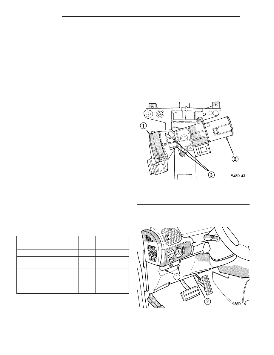
Fig. 7 Ignition Switch—Viewed From Below Column

1 - IGNITION SWITCH
2 - LOCK CYLINDER HOUSING
3 - RETAINING TABS

Fig. 8 Steering Column Cover

1 - SCREWS
2 - STEERING COLUMN COVER

19 - 14

COLUMN

RS

COLUMN (Continued)

(3) Remove parking brake release cable from han-

dle (Fig. 9).

(4) Remove

screws

holding

steering

column

shrouds (Fig. 10)and remove lower shroud.

(5) Place key cylinder in RUN position. Depress

lock cylinder retaining tab and remove key cylinder
(Fig. 11).

(6) Remove ignition switch mounting screw (Fig.

12) with a #10 Torx

t tamper proof bit.

(7) Depress retaining tab (Fig. 8) or (Fig. 13) and

gently pry ignition switch from steering column (Fig.
14).

(8) Disconnect electrical connectors from ignition

switch and remove switch (Fig. 15).

Fig. 9 Parking Brake Release Cable

1 - PARKING BRAKE CABLE
2 - PARKING BRAKE HANDLE

Fig. 10 Steering Column Shroud Screws

1 - STEERING WHEEL
2 - SCREWS
3 - LOWER STEERING COLUMN SHROUD

Fig. 11 Lock Cylinder Retaining Tab

1 - IGNITION SWITCH
2 - RETAINING TAB

Fig. 12 Ignition Switch Mounting Screw

1 - MOUNTING SCREW
2 - IGNITION SWITCH

RS

COLUMN

19 - 15

IGNITION SWITCH (Continued)

INSTALLATION

The ignition switch attaches to the lock cylinder

housing on the end opposite the lock cylinder (Fig. 7)
. For ignition switch terminal and circuit identifica-
tion, refer to the Wiring Diagrams section.

(1) Ensure the ignition switch is in the RUN posi-

tion and the actuator shaft in the lock housing is in
the RUN position.

(2) Install electrical connectors to ignition switch.
(3) Carefully

install

the

ignition

switch.

The

switch will snap over the retaining tabs (Fig. 16) .
Install mounting screw (Fig. 12).

(4) Install upper and lower shrouds.

(5) Install key cylinder (cylinder retaining tab will

depress only in the RUN position).

(6) Connect negative cable to battery.

(7) Check for proper operation of ignition switch

and key-in warning switch.

Fig. 13 Ignition Switch Retaining Tab

1 - IGNITION SWITCH
2 - RETAINING TAB

Fig. 14 Removing Ignition Switch

1 - IGNITION SWITCH
2 - RETAINING TAB

Fig. 15 Ignition Switch Connectors

1 - KEY IN SWITCH
2 - PRNDL SWITCH
3 - IGNITION SWITCH

Fig. 16 Ignition Switch Installation

1 - IGNITION SWITCH
2 - ACTUATOR SHAFT
3 - RETAINING TABS

19 - 16

COLUMN

RS

IGNITION SWITCH (Continued)

LOCK CYLINDER HOUSING

DESCRIPTION - IGNITION INTERLOCK

All vehicles equipped with automatic transaxles

have an interlock system. The system prevents shift-
ing the vehicle out of Park unless the ignition lock
cylinder is in the Unlock, Run or Start position. In
addition, the operator cannot rotate the key to the
lock position unless the shifter is in the park posi-
tion. On vehicles equipped with floor shift refer to
the - Transaxle for Automatic Transmission Shifter/
Ignition Interlock.

REMOVAL

NOTE: Before proceeding, review all Steering Col-
umn and Airbag Warnings and Cautions. (Refer to
19 - STEERING/COLUMN - WARNING)(Refer to 8 -
ELECTRICAL/RESTRAINTS - WARNING)

(1) Remove battery ground cable terminal from

battery negative post and isolate.

(2) Under instrument panel, remove silencer panel

below lower steering column cover.

(3) Remove screws securing lower steering column

cover/knee blocker, then remove it (Fig. 17).

(4) Disconnect

parking

brake

release

link

at

release handle.

(5) Compress tabs on sides of data link diagnostic

connector and remove it from knee blocker reinforce-
ment plate.

(6) Remove screws securing knee blocker reinforce-

ment plate in place, then remove reinforcement plate
(Fig. 17).

(7) Remove the upper and lower column shrouds.

(Refer

to

19

-

STEERING/COLUMN/LOWER

SHROUD - REMOVAL)

(8) Unsnap the trim bezel on the instrument panel

between the instrument cluster and the steering col-
umn.

(9) Remove the 2 screws securing the steering col-

umn fixed shroud to the steering column (Fig. 18),
then remove the shroud.

(10) Remove the two screws holding the metal

cover in place below the shifter/ignition interlock
linkage (Fig. 19), then remove the cover.

Fig. 17 Lower Steering Column Cover And

Reinforcement

1 - INSTRUMENT PANEL
2 - REINFORCEMENT PLATE
3 - LOWER STEERING COLUMN COVER/KNEE BLOCKER

Fig. 18 Fixed Shroud Mounting

1 - SCREWS
2 - SHROUD

Fig. 19 Cover Removal/Installation

1 - IGNITION SWITCH
2 - SCREW
3 - COVER

RS

COLUMN

19 - 17


Content   ..  351  352  353  354   ..