Chrysler Town, Dodge Caravan. Manual - part 344


  Index      Chrysler     Chrysler TOWN & COUNTRY, VOYAGER, Dodge Caravan - service repair manual 2001-2007 year


Search            


Content   ..  342  343  344  345   ..


Chrysler Town, Dodge Caravan. Manual - part 344


WARNING: RELEASE FUEL SYSTEM PRESSURE
BEFORE DISCONNECTING A QUICK-CONNECT FIT-
TINGS. REFER TO THE FUEL PRESSURE RELEASE
PROCEDURE.

(1) Perform

Fuel

Pressure

Release

Procedure.

Refer to the Fuel Pressure Release Procedure in this
section.

(2) Disconnect negative cable from battery or aux-

iliary jumper terminal.

(3) Squeeze retainer tabs together and pull fuel

tube/quick-connect fitting assembly off of fuel tube
nipple. The retainer will remain on fuel tube.

INSTALLATION

CAUTION: Never install a quick-connect fitting with-
out the retainer being either on the fuel tube or
already in the quick-connect fitting. In either case,
ensure the retainer locks securely into the quick-
connect fitting by firmly pulling on fuel tube and fit-
ting to ensure it is secured.

(1) Using a clean lint free cloth, clean the fuel tube

nipple and retainer.

(2) Prior to connecting the fitting to the fuel tube,

coat the fuel tube nipple with clean engine oil.

(3) Push the quick-connect fitting over the fuel

tube until the retainer seats and a click is heard.

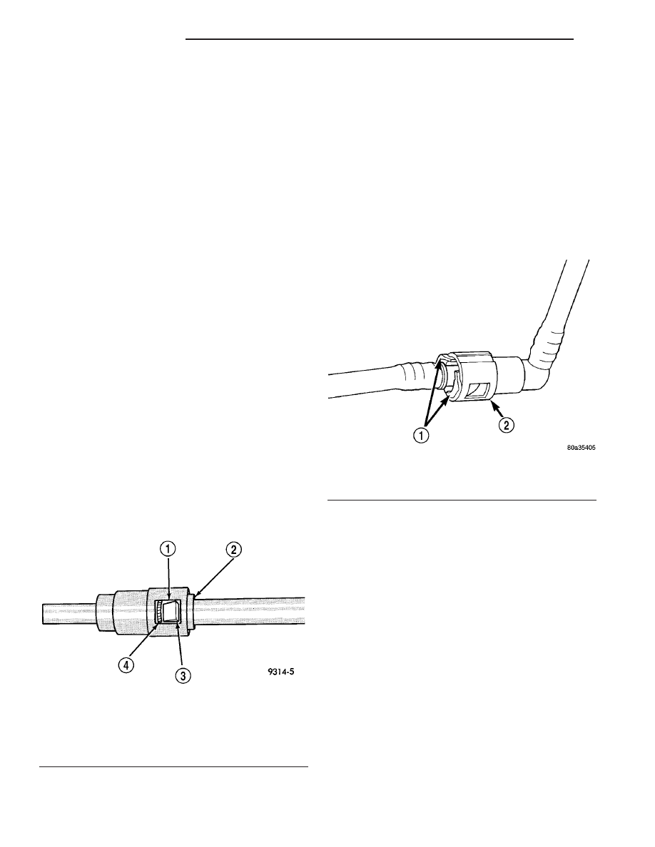
(4) The plastic quick-connect fitting has windows

in the sides of the casing. When the fitting com-
pletely attaches to the fuel tube, the retainer locking
ears and the fuel tube shoulder are visible in the
windows. If they are not visible, the retainer was not
properly installed (Fig. 24). Do not rely upon the
audible click to confirm a secure connection.

(5) Connect negative cable to battery or auxiliary

jumper terminal.

CAUTION: When using the ASD Fuel System Test,
the Auto Shutdown (ASD) Relay remains energized
for several minutes, until the test is stopped, or
until the ignition switch is turned to the Off posi-
tion.

(6) Use the DRB III

t scan tool ASD Fuel System

Test to pressurize the fuel system. Check for leaks.

TWO-TAB TYPE FITTING

This type of fitting is equipped with tabs located on

both sides of the fitting (Fig. 25). These tabs are sup-
plied for disconnecting the quick-connect fitting from
component being serviced.

CAUTION: The interior components (O-rings, spac-
ers) of this type of quick-connect fitting are not ser-
viced separately, but new plastic retainers are
available. Do not attempt to repair damaged fittings
or fuel lines/tubes. If repair is necessary, replace
the complete fuel tube assembly.

WARNING: THE FUEL SYSTEM IS UNDER A CON-
STANT PRESSURE (EVEN WITH THE ENGINE OFF).
BEFORE SERVICING ANY FUEL SYSTEM HOSES,
FITTINGS OR LINES, THE FUEL SYSTEM PRES-
SURE MUST BE RELEASED. REFER TO THE FUEL
PRESSURE

RELEASE

PROCEDURE

IN

THIS

GROUP.

DISCONNECTION/CONNECTION

(1) Perform fuel pressure release procedure. Refer

to Fuel Pressure Release Procedure in this group.

(2) Disconnect negative battery cable from battery

or auxiliary jumper terminal.

Fig. 24 Plastic Quick-Connect Fitting/Fuel Tube

Connection

1 - WINDOW
2 - TAB (2)
3 - EAR
4 - SHOULDER (ON TUBE)

Fig. 25 Typical Two-Tab Type Quick-Connect Fitting

1 - TAB(S)
2 - QUICK-CONNECT FITTING

14 - 14

FUEL DELIVERY

RS

QUICK CONNECT FITTING (Continued)

(3) Clean fitting of any foreign material before dis-

assembly.

(4) To disconnect quick-connect fitting, squeeze

plastic retainer tabs (Fig. 25) against sides of quick-
connect fitting with your fingers. Tool use is not
required

for

removal

and

may

damage

plastic

retainer. Pull fitting from fuel system component
being serviced. The plastic retainer will remain on
component being serviced after fitting is discon-
nected. The O-rings and spacer will remain in quick-
connect fitting connector body.

(5) Inspect quick-connect fitting body and compo-

nent for damage. Replace as necessary.

CAUTION: When the quick-connect fitting was dis-
connected, the plastic retainer will remain on the
component being serviced. If this retainer must be
removed, very carefully release the retainer from
the component with two small screwdrivers. After
removal, inspect the retainer for cracks or any dam-
age.

(6) Prior to connecting quick-connect fitting to

component being serviced, check condition of fitting
and component. Clean parts with a lint-free cloth.
Lubricate with clean engine oil.

(7) Insert quick-connect fitting to component being

serviced and into plastic retainer. When a connection
is made, a click will be heard.

(8) Verify a locked condition by firmly pulling on

fuel tube and fitting (15-30 lbs.).

(9) Connect negative cable to battery or auxiliary

jumper terminal.

(10) Use the DRB III

t scan tool ASD Fuel System

Test to pressurize the fuel system. Check for leaks.

PLASTIC RETAINER RING TYPE FITTING

This type of fitting can be identified by the use of a

full-round plastic retainer ring (Fig. 26) usually black
in color.

CAUTION: The interior components (O-rings, spac-
ers, retainers) of this type of quick-connect fitting
are not serviced separately. Do not attempt to repair
damaged fittings or fuel lines/tubes. If repair is nec-
essary, replace the complete fuel tube assembly.

WARNING: THE FUEL SYSTEM IS UNDER A CON-
STANT PRESSURE (EVEN WITH THE ENGINE OFF).
BEFORE SERVICING ANY FUEL SYSTEM HOSES,
FITTINGS OR LINES, THE FUEL SYSTEM PRES-
SURE MUST BE RELEASED. REFER TO THE FUEL
SYSTEM PRESSURE RELEASE PROCEDURE IN
THIS GROUP.

DISCONNECTION/CONNECTION

(1) Perform fuel pressure release procedure. Refer

to Fuel Pressure Release Procedure in this section.

(2) Disconnect negative battery cable from battery

or auxiliary jumper terminal.

(3) Clean fitting of any foreign material before dis-

assembly.

(4) To release fuel system component from quick-

connect fitting, firmly push fitting towards compo-
nent being serviced while firmly pushing plastic
retainer ring into fitting (Fig. 26). With plastic ring
depressed, pull fitting from component. The plastic
retainer ring must be pressed squarely into fit-
ting body. If this retainer is cocked during
removal, it may be difficult to disconnect fit-
ting. Use an open-end wrench on shoulder of
plastic retainer ring to aid in disconnection.

(5) After disconnection, plastic retainer ring will

remain with quick-connect fitting connector body.

(6) Inspect fitting connector body, plastic retainer

ring and fuel system component for damage. Replace
as necessary.

(7) Prior to connecting quick-connect fitting to

component being serviced, check condition of fitting
and component. Clean parts with a lint-free cloth.
Lubricate with clean engine oil.

Fig. 26 Plastic Retainer Ring Type Fitting

1 - FUEL TUBE
2 - QUICK CONNECT FITTING
3 - PUSH
4 - PLASTIC RETAINER
5 - PUSH
6 - PUSH
7 - PUSH
8 - PUSH

RS

FUEL DELIVERY

14 - 15

QUICK CONNECT FITTING (Continued)

(8) Insert quick-connect fitting into component

being serviced until a click is felt.

(9) Verify a locked condition by firmly pulling on

fuel tube and fitting (15-30 lbs.).

(10) Connect negative battery cable to battery or

auxiliary jumper terminal.

(11) Use the DRB III

t scan tool ASD Fuel System

Test to pressurize the fuel system. Check for leaks.

14 - 16

FUEL DELIVERY

RS

QUICK CONNECT FITTING (Continued)

FUEL INJECTION

TABLE OF CONTENTS

page

page

FUEL INJECTION

OPERATION

OPERATION - INJECTION SYSTEM

. . . . . . . 18

OPERATION - MODES OF OPERATION

. . . . 18

FUEL CORRECTION or ADAPTIVE

MEMORIES . . . . . . . . . . . . . . . . . . . . . . . . . . 20

PROGRAMMABLE COMMUNICATIONS

INTERFACE (PCI) BUS . . . . . . . . . . . . . . . . . 21

SYSTEM DIAGNOSIS

. . . . . . . . . . . . . . . . . . 22

SPECIFICATIONS

TORQUE

. . . . . . . . . . . . . . . . . . . . . . . . . . . . 22

SPECIAL TOOLS

FUEL

. . . . . . . . . . . . . . . . . . . . . . . . . . . . . . . 23

ACCELERATOR PEDAL

REMOVAL

. . . . . . . . . . . . . . . . . . . . . . . . . . . . . 23

INSTALLATION

. . . . . . . . . . . . . . . . . . . . . . . . . 24

CRANKSHAFT POSITION SENSOR

DESCRIPTION

. . . . . . . . . . . . . . . . . . . . . . . . . 24

OPERATION

. . . . . . . . . . . . . . . . . . . . . . . . . . . 24

REMOVAL

. . . . . . . . . . . . . . . . . . . . . . . . . . . . . 25

INSTALLATION - 2.4L

. . . . . . . . . . . . . . . . . . . . 25

ENGINE SPEED SENSOR

DESCRIPTION

. . . . . . . . . . . . . . . . . . . . . . . . . 25

OPERATION

. . . . . . . . . . . . . . . . . . . . . . . . . . . 26

FUEL INJECTOR

DESCRIPTION

. . . . . . . . . . . . . . . . . . . . . . . . . 26

OPERATION

. . . . . . . . . . . . . . . . . . . . . . . . . . . 26

REMOVAL

REMOVAL - 2.4L

. . . . . . . . . . . . . . . . . . . . . . 26

REMOVAL - 3.3/3.8L

. . . . . . . . . . . . . . . . . . . 27

INSTALLATION

INSTALLATION - 2.4L

. . . . . . . . . . . . . . . . . . 27

INSTALLATION - 3.3/3.8L

. . . . . . . . . . . . . . . . 27

FUEL PUMP RELAY

DESCRIPTION

. . . . . . . . . . . . . . . . . . . . . . . . . 28

OPERATION

. . . . . . . . . . . . . . . . . . . . . . . . . . . 28

IDLE AIR CONTROL MOTOR

DESCRIPTION

. . . . . . . . . . . . . . . . . . . . . . . . . 28

OPERATION

. . . . . . . . . . . . . . . . . . . . . . . . . . . 28

REMOVAL

. . . . . . . . . . . . . . . . . . . . . . . . . . . . . 29

INSTALLATION

. . . . . . . . . . . . . . . . . . . . . . . . . 29

INLET AIR TEMPERATURE SENSOR

DESCRIPTION

. . . . . . . . . . . . . . . . . . . . . . . . . 29

OPERATION

. . . . . . . . . . . . . . . . . . . . . . . . . . . 29

MAP SENSOR

DESCRIPTION

. . . . . . . . . . . . . . . . . . . . . . . . . 30

OPERATION

. . . . . . . . . . . . . . . . . . . . . . . . . . . 30

REMOVAL

REMOVAL - 2.4L

. . . . . . . . . . . . . . . . . . . . . . 31

REMOVAL - 3.3/3.8L

. . . . . . . . . . . . . . . . . . . 31

INSTALLATION

INSTALLATION - 2.4L

. . . . . . . . . . . . . . . . . . 31

INSTALLATION - 3.3/3.8L

. . . . . . . . . . . . . . . . 31

O2 SENSOR

DESCRIPTION

. . . . . . . . . . . . . . . . . . . . . . . . . 31

OPERATION

. . . . . . . . . . . . . . . . . . . . . . . . . . . 31

REMOVAL

REMOVAL - UPSTREAM 1/1 - 2.4L

. . . . . . . . 33

REMOVAL - UPSTREAM 1/1 - 3.3/3.8L

. . . . . 33

REMOVAL - DOWNSTREAM 1/2 - 2.4/3.3/

3.8L . . . . . . . . . . . . . . . . . . . . . . . . . . . . . . . . 33

INSTALLATION

INSTALLATION - UPSTREAM 1/1 - 2.4L

. . . . . 33

INSTALLATION - UPSTREAM 1/1 - 3.3/3.8L

. . 34

INSTALLATION DOWNSTREAM 2/1 -

2.4/3.3/3.8L . . . . . . . . . . . . . . . . . . . . . . . . . . 34

THROTTLE BODY

DESCRIPTION

. . . . . . . . . . . . . . . . . . . . . . . . . 34

OPERATION

. . . . . . . . . . . . . . . . . . . . . . . . . . . 34

REMOVAL

. . . . . . . . . . . . . . . . . . . . . . . . . . . . . 35

INSTALLATION

. . . . . . . . . . . . . . . . . . . . . . . . . 35

THROTTLE CONTROL CABLE

REMOVAL

. . . . . . . . . . . . . . . . . . . . . . . . . . . . . 35

INSTALLATION

. . . . . . . . . . . . . . . . . . . . . . . . . 35

THROTTLE POSITION SENSOR

DESCRIPTION

. . . . . . . . . . . . . . . . . . . . . . . . . 36

OPERATION

. . . . . . . . . . . . . . . . . . . . . . . . . . . 36

REMOVAL - 3.3/3.8L

. . . . . . . . . . . . . . . . . . . . . 36

INSTALLATION - 3.3/3.8L

. . . . . . . . . . . . . . . . . 36

RS

FUEL INJECTION

14 - 17


Content   ..  342  343  344  345   ..