Chrysler Town, Dodge Caravan. Manual - part 342


  Index      Chrysler     Chrysler TOWN & COUNTRY, VOYAGER, Dodge Caravan - service repair manual 2001-2007 year


Search            


Content   ..  340  341  342  343   ..


Chrysler Town, Dodge Caravan. Manual - part 342


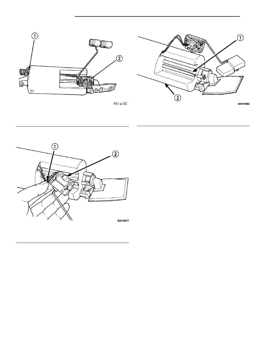
(2) Wrap wires into groove in back of level sensor

(Fig. 7) .

(3) While feeding wires into guide grooves, slide

level sensor up into channel until it snaps into place
(Fig. 8) . Ensure tab at bottom of sensor locks in
place.

(4) Install level sensor wires in connector. Push

the wires up through the connector and then pull
them down until they lock in place. Ensure signal
and ground wires are installed in the correct posi-
tion.

(5) Install locking wedge on connector.
(6) Push connector up into bottom of fuel pump

module electrical connector.

(7) Install fuel pump module. Refer to Fuel Pump

Module in this section.

FUEL LINES

DESCRIPTION - FUEL LINES/HOSES AND
CLAMPS

Also refer to Quick-Connect Fittings.

WARNING: THE FUEL SYSTEM IS UNDER A CON-
STANT PRESSURE (EVEN WITH THE ENGINE OFF).
BEFORE SERVICING ANY FUEL SYSTEM HOSES,
FITTINGS OR LINES, THE FUEL SYSTEM PRES-
SURE MUST BE RELEASED. REFER TO THE FUEL
SYSTEM PRESSURE RELEASE PROCEDURE IN
THIS GROUP.

The lines/tubes/hoses used on fuel injected vehicles

are of a special construction. This is due to the
higher fuel pressures and the possibility of contami-
nated fuel in this system. If it is necessary to replace
these lines/tubes/hoses, only those marked EFM/EFI
may be used.

If equipped: The hose clamps used to secure rub-

ber hoses on fuel injected vehicles are of a special
rolled edge construction. This construction is used to
prevent the edge of the clamp from cutting into the
hose. Only these rolled edge type clamps may be
used in this system. All other types of clamps may
cut into the hoses and cause high-pressure fuel leaks.

Use new original equipment type hose clamps.

STANDARD PROCEDURE - HOSES AND CLAMP

Inspect all hose connections (clamps and quick con-

nect fittings) for completeness and leaks. Replace
cracked, scuffed, or swelled hoses. Replace hoses that
rub against other vehicle components or show sign of
wear.

Fuel injected vehicles use specially constructed

hoses. When replacing hoses, only use hoses marked
EFM/EFI.

Fig. 6 Level Sensor Removal/Installation

1 - OPENING IN MODULE
2 - FUEL LEVEL SENSOR

Fig. 7 Groove in Back Side of Level Sensor

1 - WRAP WIRES IN GROOVE
2 - REAR VIEW OF LEVEL SENSOR

Fig. 8 Installation Channel

1 - CHANNEL FOR LEVEL SENSOR
2 - PUMP MODULE

14 - 6

FUEL DELIVERY

RS

FUEL LEVEL SENDING UNIT / SENSOR (Continued)

When installing hoses, ensure that they are routed

away from contact with other vehicle components
that could rub against them and cause failure. Avoid
contact with clamps or other components that cause
abrasions or scuffing. Ensure that rubber hoses are
properly routed and avoid heat sources.

The hose clamps have rolled edges to prevent the

clamp from cutting into the hose. Only use clamps
that are original equipment or equivalent. Other
types of clamps may cut into the hoses and cause
high pressure fuel leaks. Tighten hose clamps to 1
N·m (9 in. lbs.) torque.

Inspect all hose connections such as clamps, cou-

plings and fittings to make sure they are secure and
leaks are not present. The component should be
replaced immediately if there is any evidence of deg-
radation that could result in failure.

Never attempt to repair a plastic fuel line/tube.

Replace as necessary.

Avoid contact of any fuel tubes/hoses with other

vehicle components that could cause abrasions or
scuffing. Be sure that the plastic fuel lines/tubes are
properly routed to prevent pinching and to avoid heat
sources.

FUEL PRESSURE REGULATOR

OPERATION

The fuel system uses a nonadjustable pressure reg-

ulator

that

maintains

fuel

system

pressure

at

approximately 400 ±34 kPa (58 ±5 psi). The fuel
pressure regulator contains a diaphragm, calibrated
spring and a fuel return valve. The spring pushes
down on the diaphragm and closes off the fuel return
port. System fuel pressure reflects the amount of fuel
pressure required to open the return port.

The pressure regulator is a mechanical device that

is NOT controlled by the PCM or engine vacuum.

REMOVAL

The fuel pressure regulator is part of the fuel

pump module (Fig. 9). Remove the fuel pump module
from the fuel tank to access the fuel pressure regula-
tor. Refer to the Fuel Pump Module removal in this
section.

(1) Spread tangs on pressure regulator retainer.
(2) Pry fuel pressure regulator out of housing.
(3) Ensure both upper and lower O-rings were

removed with regulator.

INSTALLATION

The fuel pressure regulator is part of the fuel

pump module. Remove the fuel pump module from
the fuel tank to access the fuel pressure regulator.

Refer to the Fuel Pump Module removal in this sec-
tion.

(1) Lightly lubricate the O-rings with clean engine

oil and place them into opening in pump module (Fig.
9).

(2) Push regulator into opening in pump module.
(3) Fold tangs on regulator retainer over tabs on

housing.

FUEL PUMP

DESCRIPTION

The electric fuel pump is located in and is part of

the fuel pump module. It is a positive displacement,
gerotor type, immersible pump with a permanent
magnet electric motor. The fuel pump module is sus-
pended in fuel in the fuel tank.

OPERATION

The pump draws fuel through a strainer and

pushes it through the motor to the outlet. The pump
contains a check valve. The valve, in the pump out-
let, maintains pump pressure during engine off con-
ditions, for a short while. It is normal for fuel
pressure to drop to zero after cooldown. The fuel
pump relay provides voltage to the fuel pump. The
fuel pump has a maximum deadheaded pressure out-
put of approximately 880 kPa (130 psi). The regula-
tor adjusts fuel system pressure to approximately
400 kpa ±34 kpa (58 psi ± 5 psi).

NOTE: Checkvalve maintains volume of fuel in the
rail and lines, not pressure.

Fig. 9 Fuel Pressure Regulator O-rings

1 - UPPER O-RING
2 - LOWER 0-RING

RS

FUEL DELIVERY

14 - 7

FUEL LINES (Continued)

FUEL PUMP MODULE

DESCRIPTION

The fuel pump module is installed in the top of the

fuel tank (Fig. 10) .

The fuel pump module contains the following:
• Electric fuel pump

• Fuel pump reservoir

• Inlet strainer

• Fuel pressure regulator

• Fuel gauge sending unit

• Fuel supply line connection
The inlet strainer, fuel pressure regulator

and fuel level sensor are the only serviceable
items. If the fuel pump or electrical wiring har-
ness requires service, replace the fuel pump
module.

The electric fuel pump is located in and is part of

the fuel pump module. It is a positive displacement,
gerotor type, immersible pump with a permanent
magnet electric motor.

OPERATION

The pump draws fuel through a strainer and

pushes it through the motor to the outlet. The pump
contains one check valve. The check valve, in the
pump outlet, maintains pump pressure during engine
off conditions. The fuel pump relay provides voltage
to the fuel pump.

The fuel pump has a maximum deadheaded pres-

sure output of approximately 880 kPa (130 psi). The
regulator adjusts fuel system pressure to approxi-
mately 400 ±34 kPa (58 ±5 psi).

FUEL PUMP ELECTRICAL CONTROL

Voltage to operate the electric pump is supplied

through the fuel pump relay. For an electrical opera-
tional description of the fuel pump refer to fuel Pump
Relay—PCM Output.

ELECTRICAL PUMP REPLACEMENT

The electric fuel pump is not serviceable. If the

fuel pump or electrical wiring harness needs replace-
ment, the complete fuel pump module must be
replaced. Perform the Fuel System Pressure Release
procedure before servicing the fuel pump.

REMOVAL

WARNING: RELEASE FUEL SYSTEM PRESSURE
BEFORE SERVICING FUEL SYSTEM COMPONENTS.
SERVICE VEHICLES IN WELL VENTILATED AREAS
AND AVOID IGNITION SOURCES. NEVER SMOKE
WHILE SERVICING THE VEHICLE.

(1) Remove fuel filler cap and perform Fuel Sys-

tem Pressure Release procedure.

(2) Disconnect

negative

cable

from

auxiliary

jumper terminal.

(3) Drain fuel tank, refer to the Fuel Tank proce-

dure in the Fuel Delivery section.

(4) Remove fuel tank, refer to the Fuel Tank

removal section.

(5) Clean top of tank to remove loose dirt and

debris.

(6) Using a brass punch and hammer remove lock-

nut to release pump module (Fig. 11).

Fig. 10 Fuel Pump Module

1 - INLET STRAINER
2 - FUEL RESERVOIR
3 - FUEL PRESSURE REGULATOR
4 - FUEL LEVEL SENSOR

Fig. 11 FUEL PUMP MODULE LOCKING RING

14 - 8

FUEL DELIVERY

RS

WARNING: THE FUEL RESERVOIR OF THE FUEL
PUMP MODULE DOES NOT EMPTY OUT WHEN THE
TANK IS DRAINED. THE FUEL IN THE RESERVOIR
MAY SPILL OUT WHEN THE MODULE IS REMOVED.

(7) Remove fuel pump module and O-ring from

tank (Fig. 12). Discard O-ring.

INSTALLATION

NOTE: Be careful not to allow dirt/debris to fall into
the fuel tank.

(1) Wipe seal area of tank clean and place a new

O-ring seal in position on pump.

(2) Position fuel pump module in tank.
(3) Tighten lockring using a brass punch and ham-

mer to install the lockring (Fig. 11).

(4) Install fuel tank, refer to the Fuel Tank instal-

lation section.

(5) Lower vehicle.
(6) Connect negative cable battery.
(7) Fill fuel tank. Use the DRB III

t scan tool to

pressurize the fuel system. Check for leaks.

(8) Install fuel filler cap.

FUEL RAIL

REMOVAL

REMOVAL - 2.4L

(1) Perform fuel system pressure release procedure

before servicing or starting repairs. Refer to
Fuel System Pressure Release Procedure in this sec-
tion.

(2) Disconnect negative cable from battery.
(3) Disconnect the wiring connectors for fuel injec-

tors harness (Fig. 13).

(4) Remove wiring harness from brackets.
(5) Disconnect the connectors from the fuel injec-

tors.

(6) Remove harness from vehicle.
(7) Remove fuel hose quick connect fitting from the

chassis tube. Refer to Fuel Hoses, Clamps and
Quick Connect Fittings in this Section. 
Place a
shop towel under the connections to absorb any fuel
spilled from the fitting.

WARNING: WRAP A SHOP TOWEL AROUND HOSES
TO CATCH ANY GASOLINE SPILLAGE.

(8) Remove fuel rail attaching bolts.
(9) Remove fuel rail. Be careful not to damage the

injector O-rings upon removal from their ports.

REMOVAL - 3.3/3.8L

(1) Perform fuel system pressure release procedure

before servicing or starting repairs. Refer to
Fuel System Pressure Release Procedure in this sec-
tion.

(2) Disconnect negative cable from battery.
(3) Remove upper intake manifold, refer to the

Engine/Manifolds/Upper Intake for more informa-
tion..

(4) Cover intake manifold with suitable cover

when servicing.

(5) Remove the fuel hose quick connect fitting from

the chassis tube. Refer to Fuel Hoses, Clamps
and Quick Connect Fittings in this Section.

WARNING: WRAP A SHOP TOWEL AROUND HOSES
TO CATCH ANY GASOLINE SPILLAGE.

(6) Remove the fuel rail attaching bolts (Fig. 14).

Fig. 12 Fuel Pump Module Removal

1 - FUEL PUMP MODULE
2 - O-RING

Fig. 13 FUEL RAIL AND INJECTORS 2.4L

1 - Fuel Injectors
2 - Fuel Rail

RS

FUEL DELIVERY

14 - 9

FUEL PUMP MODULE (Continued)


Content   ..  340  341  342  343   ..