Chrysler Town, Dodge Caravan. Manual - part 343


  Index      Chrysler     Chrysler TOWN & COUNTRY, VOYAGER, Dodge Caravan - service repair manual 2001-2007 year


Search            


Content   ..  341  342  343  344   ..


Chrysler Town, Dodge Caravan. Manual - part 343


(7) Remove fuel rail. Be careful not to damage the

injector O-rings upon removal from their ports.

INSTALLATION

INSTALLATION - 2.4L

(1) Ensure

injector

holes

are

clean.

Replace

O-rings if damaged.

(2) Lubricate injector O-rings with a drop of clean

engine oil to ease installation.

(3) Put the tip of each injector into their ports.

Push the assembly into place until the injectors are
seated in the ports.

(4) Install the fuel rail mounting bolts. Tighten

bolts to 22 N·m (200 in. lbs.) torque.

(5) Connect the connectors to the fuel injectors.
(6) Install wiring harness to brackets.
(7) Connect the wiring connectors to fuel injectors

harness (Fig. 13).

(8) Connect negative battery cable.
(9) Use the DRBIII

t scan tool to pressurize the

fuel system. Check for leaks.

INSTALLATION - 3.3/3.8L

(1) Ensure

injector

holes

are

clean.

Replace

O-rings if damaged.

(2) Lubricate injector O-rings with a drop of clean

engine oil to ease installation.

(3) Put the tip of each injector into their ports.

Push the assembly into place until the injectors are
seated in the ports.

(4) Install the fuel rail mounting bolts. Tighten

bolts to 22 N·m (200 in. lbs.) torque.

(5) Remove covering on lower intake manifold and

clean surface.

(6) Install the Upper Intake Manifold, refer to

Engine/Manifolds/Upper Intake for more information.

(7) Install fuel hose quick connector fitting to chas-

sis tubes. Refer to Fuel Hoses, Clamps and
Quick Connect Fittings in this Section. 
Push the
fitting onto the chassis tube until it clicks into place.
Pull on the fitting to ensure complete insertion.

(8) Connect negative cable to battery.
(9) Use the DRBIII

t scan tool to pressurize the

fuel system. Check for leaks.

FUEL TANK

DESCRIPTION

The fuel tank is constructed of a plastic material.

Its main functions are for fuel storage and for place-
ment of the fuel pump module. The tank is made
from High density Polyethylene (HDPE) material.If
equipped with ORVR (Onboard Refueling Vapor
Recovery) it has been added to the fuel tank to con-
trol refueling vapor emissions.

OPERATION

All models pass a full 360 degree rollover test

without fuel leakage. To accomplish this, fuel and
vapor flow controls are required for all fuel tank con-
nections.

All models are equipped with either one or two

rollover valves mounted into the top of the fuel tank
(or pump module).

An evaporation control system is connected to the

rollover valve(s)/control valve(Refer to 25 - EMIS-
SIONS

CONTROL/EVAPORATIVE

EMISSIONS/

ORVR - OPERATION) to reduce emissions of fuel
vapors into the atmosphere, when the tank is vented
due to vapor expansion in the tank. When fuel evap-
orates from the fuel tank, vapors pass through vent
hoses or tubes to a charcoal canister where they are
temporarily held. When the engine is running, the
vapors are drawn into the intake manifold. In addi-
tion, fuel vapors produced during vehicle refueling
are allowed to pass through the vent hoses/tubes to
the charcoal canister(s) for temporary storage (prior
to being drawn into the intake manifold). All models
are equipped with a self-diagnosing system using a
Leak Detection Pump (LDP) or Natural Vacuum
Leak Detection (NVLD). Refer to the Emission Con-
trol System for additional information.

INLET CHECK VALVE

All vehicles have an inlet check valve on the inside

of the fuel tank at the filler inlet

The valve prevents fuel from splashing back on

customer during vehicle refueling. The valve is a
non-serviceable item.

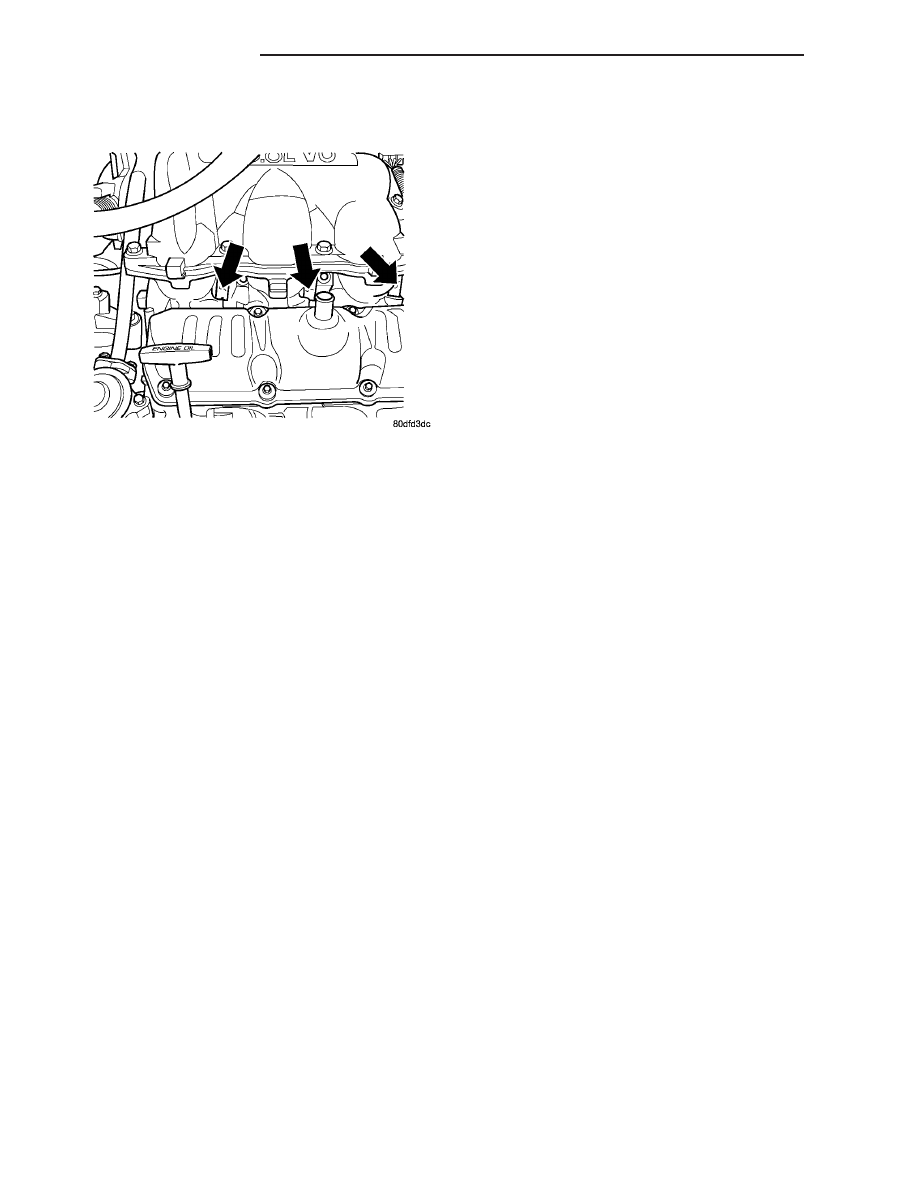
Fig. 14 FUEL INJECTORS 3.3/3.8L

14 - 10

FUEL DELIVERY

RS

FUEL RAIL (Continued)

REMOVAL

(1) Remove fuel filler cap and perform Fuel Sys-

tem Pressure Release procedure (Fig. 15).

(2) Disconnect negative cable from battery.
(3) Insert fuel siphon hose into fuel filler neck and

push it into the tank.

(4) Drain fuel tank dry into holding tank or a

properly labeled GASOLINE safety container.

(5) Raise vehicle on hoist and support.
(6) Use a transmission jack to support fuel tank.

Remove bolts from fuel tank straps.

(7) Lower tank slightly.
(8) Disconnect the fuel filler vent tube. Squeeze

tabs and pull apart (Fig. 16).

(9) Disconnect the fuel fill hose at the fuel tank

filler metal tube NOT AT THE FUEL TANK (Fig.
16).

(10) Disconnect fuel line and vapor line at the

front of the fuel tank.

The fuel pump module electrical connector

has a retainer that locks it in place.

(11) Slide fuel pump module electrical connector

lock to unlock (Fig. 17).

(12) Push down on connector retainer (Fig. 18) and

pull connector off module.

(13) Lower tank from vehicle. Remove fuel filler

vent tube from frame (Fig. 19).

INSTALLATION

(1) Position fuel tank on transmission jack. Con-

nect rollover valve hose. Connect fuel filler tube vent
hose and tighten clamp.

(2) Raise tank into position and carefully work

filler metal tube into the rubber hose on fuel tank. A
light coating of clean engine oil on the tube end may
be used to aid assembly.

(3) Feed filler vent line thru frame rail. Careful

not to cross lines.

Fig. 15 Fuel Tank

1 - ROLLOVER VALVE
2 - FUEL FILLER INLET
3 - ROLLOVER VALVE
4 - GROUND STRAP
5 - FUEL FILTER
6 - FUEL PUMP MODULE

Fig. 16 FUEL FILLER AND VENT TUBE

1 - Filler Tube
2 - Vent Tube

Fig. 17 Fuel Line Retainers and Pump Connector

Lock

1 - PUSH
2 - CONNECTOR LOCK
3 - QUICK CONNECT RETAINERS

RS

FUEL DELIVERY

14 - 11

FUEL TANK (Continued)

(4) Tighten strap bolts to 54 N·m (40 ft. lbs.)

torque. Tighten T strap bolt to 28.2 N·m (250 in.
lbs.). Remove transmission jack.

(5) Tighten filler hose clamp to 3.3 N·m (30 in.

lbs.).

CAUTION: Ensure straps are not twisted or bent
before or after tightening strap nuts.

(6) Connect fuel pump/module electrical connector.

Place retainer in locked position.

(7) Lubricate the fuel supply line with clean 30

weight engine oil, install the quick connect fuel fit-

ting. Refer to Tube/Fitting Assembly in the Fuel
Delivery section of this section.

(8) Connect the control vapor line at rear of tank.
(9) Attach filler vent line to filler tube. Pull on

connector to make sure of connection.

(10) Fill fuel tank, replace cap, and connect bat-

tery negative cable.

(11) Use the DRBIII

t scan tool to pressurize the

fuel system. Check for leaks.

FUEL TANK FILLER TUBE

REMOVAL

(1) Disconnect the negative battery cable.
(2) Remove the 3 screws at the filler door.
(3) Raise and support vehicle
(4) Remove the left rear tire.
(5) Remove the splash shield (Fig. 20) or (Fig. 21).

(6) Remove the canister from filler tube (Fig. 22).
(7) Disconnect the vent at the top of the filler tube.
(8) Remove the ground strap.
(9) Remove filler tube at tank.

INSTALLATION

(1) Install filler tube to tank (Fig. 20).
(2) Install the ground strap.
(3) Connect the vent at the top of the filler tube.
(4) Install the 3 screws at the filler door.

Fig. 18 Pump Module Connector Retainer and Lock

1 - PUSH DOWN ON RETAINER
2 - CONNECTOR LOCK

Fig. 19 VENT HOSE

Fig. 20 FUEL FILLER TUBE AND VENT TUBE (RG)

14 - 12

FUEL DELIVERY

RS

FUEL TANK (Continued)

(5) Install the canister from filler tube (Fig. 22).
(6) Install the splash shield.
(7) Install the left rear tire.
(8) lower vehicle.
(9) Connect the negative battery cable.

INLET FILTER

REMOVAL

(1) Remove fuel pump module. Refer to Fuel Pump

Module Removal in this section.

(2) Using a thin straight blade screwdriver, pry

back the locking tabs on fuel pump reservoir and
remove the strainer (Fig. 23).

(3) Remove strainer O-ring from the fuel pump

reservoir body.

(4) Remove any contaminants in the fuel tank by

washing the inside of the fuel tank.

INSTALLATION

(1) Lubricate the strainer O-ring with clean engine

oil.

(2) Insert strainer O-ring into outlet of strainer so

that it sits evenly on the step inside the outlet.

(3) Push strainer onto the inlet of the fuel pump

reservoir body. Make sure the locking tabs on the
reservoir body lock over the locking tangs on the
strainer.

(4) Install fuel pump module. Refer to Fuel Pump

Module Installation in this section.

QUICK CONNECT FITTING

STANDARD PROCEDURE - QUICK-CONNECT
FITTINGS

REMOVAL

When disconnecting a quick-connect fitting, the

retainer will remain on the fuel tube nipple.

Fig. 21 FUEL FILLER TUBE (RS)

Fig. 22 FUEL TUBE VENT CANISTER

Fig. 23 Inlet

1 - TABS
2 - INLET STRAINER

RS

FUEL DELIVERY

14 - 13

FUEL TANK FILLER TUBE (Continued)


Content   ..  341  342  343  344   ..