Chrysler Town, Dodge Caravan. Manual - part 334


  Index      Chrysler     Chrysler TOWN & COUNTRY, VOYAGER, Dodge Caravan - service repair manual 2001-2007 year


Search            


Content   ..  332  333  334  335   ..


Chrysler Town, Dodge Caravan. Manual - part 334


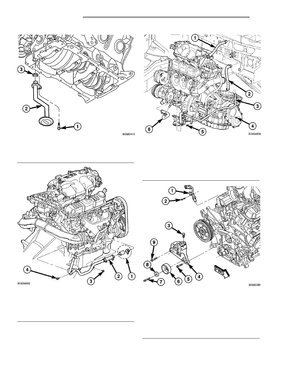
(16) Remove camshaft position sensor from timing

chain cover (Fig. 136).

Fig. 133 OIL PICKUP TUBE

1 - BOLT
2 - OIL PICK-UP TUBE
3 - O-RING

Fig. 134 HEATER RETURN HOSE (Without Engine

Oil Cooler)

1 - CAP AND CLAMP (OIL COOLER EQUIPPED ONLY)
2 - HOSE ASSEMBLY - HEATER RETURN
3 - BOLT - HEATER TUBE ATTACHING
4 - BOLT - HEATER TUBE ATTACHING

Fig. 135 HEATER HOSES 3.3/3.8L (With Engine Oil

Cooler)

1 - HOSE - HEATER SUPPLY
2 - HOSE - HEATER RETURN
3 - TUBE ASSEMBLY - HEATER RETURN
4 - BOLT - TUBE ASSEMBLY
5 - BOLT - TUBE ASSEMBLY
6 - HOSE - HEATER RETURN/OIL COOLER OUTLET

Fig. 136 Engine Mount Bracket

1 - CAMSHAFT SENSOR
2 - BOLT - CAMSHAFT SENSOR
3 - BOLT - MOUNT BRACKET (VERTICAL)
4 - BRACKET - ENGINE MOUNT
5 - BOLT - MOUNT BRACKET (HORIZONTAL)
6 - PULLEY - IDLER
7 - BOLT - IDLER PULLEY
8 - SPACER - IDLER PULLEY BOLT
9 - BOLT - MOUNT BRACKET (HORIZONTAL)

9 - 154

ENGINE 3.3/3.8L

RS

TIMING CHAIN COVER (Continued)

(17) Remove the water pump for cover removal

clearance. (Refer to 7 - COOLING/ENGINE/WATER
PUMP - REMOVAL)

(18) Remove the bolt attaching the power steering

pump support strut to the front cover (Fig. 137).

(19) Remove the timing chain cover fasteners.

Remove timing chain cover (Fig. 138).

INSTALLATION

(1) Be sure mating surfaces of chain case cover

and cylinder block are clean and free from burrs.
Crankshaft oil seal must be removed to insure cor-
rect oil pump engagement.

NOTE: DO NOT USE SEALER ON COVER GASKET

(2) Position new gasket on timing cover (Fig. 138).

Adhere new gasket to chain case cover, making sure
that the lower edge of the gasket is flush to 0.5 mm
(0.020 in.) passed the lower edge of the cover.

(3) Rotate crankshaft so that the oil pump drive

flats are in the vertical position.

(4) Position oil pump inner rotor so the mating

flats are in the same position as the crankshaft drive
flats (Fig. 138).

CAUTION: Make sure the oil pump is engaged on
the crankshaft correctly or severe damage may
result.

(5) Install timing cover (Fig. 138).
(6) Install timing chain cover bolts. Tighten M8

bolts to 27 N·m (20 ft. lbs.) and M10 bolts to 54 N·m
(40 ft. lbs.) (Fig. 139).

(7) Install crankshaft front oil seal. (Refer to 9 -

ENGINE/ENGINE

BLOCK/CRANKSHAFT

OIL

SEAL - FRONT - INSTALLATION)

(8) Install water pump and pulley. (Refer to 7 -

COOLING/ENGINE/WATER PUMP - INSTALLA-
TION)

(9) Install crankshaft vibration damper. (Refer to 9

- ENGINE/ENGINE BLOCK/VIBRATION DAMPER -
INSTALLATION)

(10) Install engine mount bracket (Fig. 136) and

tighten M10 to 54 N·m (40 ft. lbs.), M8 bolt to 28
N·m (21 ft. lb. lbs.).

(11) Install idler pulley on engine mount bracket

(Fig. 136).

(12) Install right side engine mount. (Refer to 9 -

ENGINE/ENGINE MOUNTING/RIGHT MOUNT -
INSTALLATION)

(13) Install camshaft position sensor (Refer to 8 -

ELECTRICAL/IGNITION

CONTROL/CAMSHAFT

POSITION SENSOR - INSTALLATION).

(14) Connect the heater return hose at rear of tim-

ing chain cover (Fig. 134) or at water pump inlet
tube (if engine oil cooler equipped) (Fig. 135).

(15) Connect the radiator lower hose.
(16) Install A/C compressor.
(17) Install accessory drive belt. (Refer to 7 -

COOLING/ACCESSORY

DRIVE/DRIVE

BELTS

-

INSTALLATION)

(18) Install oil pump pick-up tube with new

O-ring. Tighten attaching bolt to 28 N·m (250 in.
lbs.).

(19) Install oil pan. (Refer to 9 - ENGINE/LUBRI-

CATION/OIL PAN - INSTALLATION)

(20) Install inner splash shield and right front

wheel.

(21) Fill crankcase with engine oil to proper level.
(22) Fill cooling system. (Refer to 7 - COOLING -

STANDARD PROCEDURE)

(23) Connect negative cable to battery.

Fig. 137 Power Steering Pump Strut

1 - BOLT - LOWER
2 - STRUT - P/S PUMP
3 - BOLT - UPPER

Fig. 138 Timing Chain Cover and Gasket

1 - GASKET
2 - TIMING CHAIN COVER

RS

ENGINE 3.3/3.8L

9 - 155

TIMING CHAIN COVER (Continued)

TIMING CHAIN AND
SPROCKETS

REMOVAL

REMOVAL - TIMING CHAIN AND CAMSHAFT
SPROCKET

(1) Disconnect negative cable from battery.
(2) Remove the timing chain cover. (Refer to 9 -

ENGINE/VALVE TIMING/TIMING BELT / CHAIN
COVER(S) - REMOVAL)

(3) Rotate engine by turning crankshaft until the

timing marks are aligned as shown in (Fig. 140).

(4) Remove camshaft sprocket attaching bolt.
(5) Remove

the

timing

chain

with

camshaft

sprocket.

(6) Remove the crankshaft sprocket. (Refer to 9 -

ENGINE/VALVE

TIMING/TIMING

BELT/CHAIN

AND SPROCKETS - REMOVAL)

REMOVAL - CRANKSHAFT SPROCKET

(1) Remove

the

timing

chain.

(Refer

to

9

-

ENGINE/VALVE

TIMING/TIMING

BELT/CHAIN

AND SPROCKETS - REMOVAL)

(2) Using Special Tools 8539, 5048-6, and 5048-1,

remove the crankshaft sprocket while holding the
crankshaft from turning (Fig. 141). Be careful not to
damage the crankshaft surfaces.

INSTALLATION

INSTALLATION - CRANKSHAFT SPROCKET

(1) Position the sprocket on the crankshaft (timing

mark out) with the timing slot aligned with the tim-
ing pin.

Fig. 139 TIMING CHAIN COVER BOLT LOCATIONS

1 - BOLT - M8 x 1.25 x 95

4 - BOLT - M8 x 1.25 x 80

2 - BOLT - M10 x 1.5 x 100

5 - BOLT - M8 x 1.25 x 45

3 - BOLT - M10 x 1.5 x 85

9 - 156

ENGINE 3.3/3.8L

RS

TIMING CHAIN COVER (Continued)

(2) Install sprocket using Special Tool 8452 (Fig.

142). Install sprocket until it is fully seats on the
crankshaft.

(3) Install the timing chain and camshaft sprocket.

(Refer to 9 - ENGINE/VALVE TIMING/TIMING
BELT/CHAIN AND SPROCKETS - INSTALLATION)

INSTALLATION - TIMING CHAIN AND
CAMSHAFT SPROCKET

(1) Rotate crankshaft so the timing arrow is to the

12 o’clock position (Fig. 140).

NOTE: Lubricate timing chain and sprockets with
clean engine oil before installation.

(2) While holding camshaft sprocket and chain in

hand, place timing chain around the sprocket, align-
ing the plated link with the dot on the sprocket. Posi-
tion the timing arrow to the 6 o’clock position (Fig.
140).

(3) Place timing chain around crankshaft sprocket

with the plated link lined up with the dot on the
sprocket. Install camshaft sprocket into position.

(4) Use a straight edge to check alignment of tim-

ing marks.

(5) Install camshaft sprocket bolt and washer.

Tighten bolt to 54 N·m (40 ft. lbs.).

(6) Rotate crankshaft 2 revolutions and check tim-

ing mark alignment (Fig. 140). If timing marks do
not line up, remove camshaft sprocket and realign.

(7) Install the timing chain cover. (Refer to 9 -

ENGINE/VALVE TIMING/TIMING BELT / CHAIN
COVER(S) - INSTALLATION)

(8) Connect negative cable to battery.

Fig. 140 Timing Mark Alignment

1 - CAMSHAFT SPROCKET TIMING MARK (DOT)
2 - PLATED LINK
3 - CRANKSHAFT SPROCKET TIMING MARK (DOT)
4 - ARROWS

Fig. 141 CRANKSHAFT SPROCKET - REMOVAL

1 - SPECIAL TOOL 5048-6
2 - SPECIAL TOOL 5048-1
3 - SPECIAL TOOL 8450
4 - CRANKSHAFT SPROCKET
5 - SPECIAL TOOL 8539

Fig. 142 CRANKSHAFT SPROCKET - INSTALLATION

1 - SPECIAL TOOL 8452-3
2 - SPECIAL TOOL 8452-1
3 - CRANKSHAFT SPROCKET
4 - THRUST BEARING / WASHER

RS

ENGINE 3.3/3.8L

9 - 157

TIMING CHAIN AND SPROCKETS (Continued)


Content   ..  332  333  334  335   ..