Chrysler Town, Dodge Caravan. Manual - part 326


  Index      Chrysler     Chrysler TOWN & COUNTRY, VOYAGER, Dodge Caravan - service repair manual 2001-2007 year


Search            


Content   ..  324  325  326  327   ..


Chrysler Town, Dodge Caravan. Manual - part 326


(2)

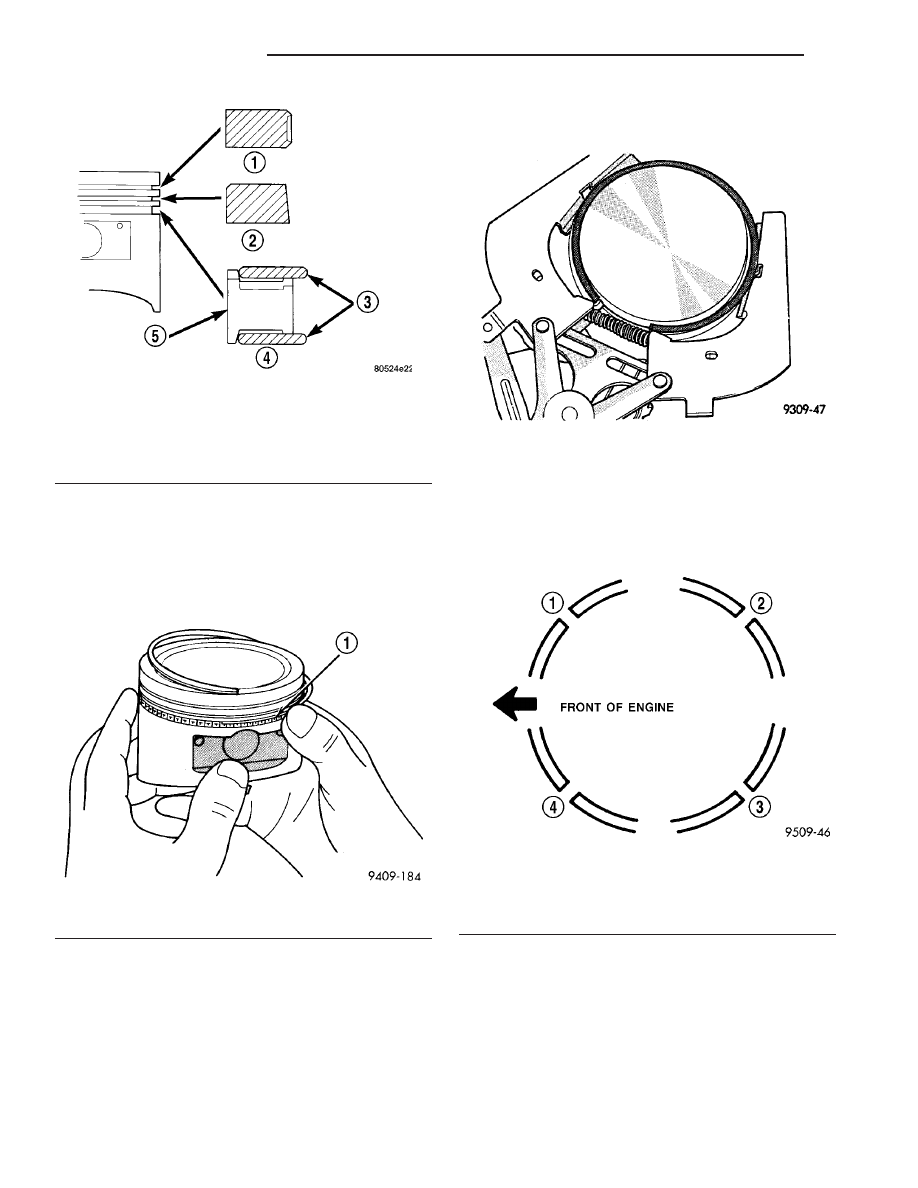
Install the side rail by placing one end

between the piston ring groove and the expander.
Hold end firmly and press down the portion to be
installed until side rail is in position. Do not use a
piston ring expander 
(Fig. 64).

(3) Install upper side rail first and then the lower

side rail.

(4) Install No. 2 piston ring and then No. 1 piston

ring (Fig. 65).

(5) Position piston ring end gaps as shown in (Fig.

66).

(6)

Position oil ring expander gap at least 45°

from the side rail gaps but not on the piston pin cen-
ter or on the thrust direction. Staggering ring gap is
important for oil control.

Fig. 63 Piston Ring Installation

1 - NO. 1 PISTON RING
2 - NO. 2 PISTON RING
3 - SIDE RAIL
4 - OIL RING
5 - SPACER EXPANDER

Fig. 64 Oil Ring Side Rail

1 - SIDE RAIL END

Fig. 65 Piston Ring Installation

Fig. 66 Piston Ring End Gap Position

1 - GAP OF LOWER SIDE RAIL
2 - NO. 1 RING GAP
3 - GAP OF UPPER SIDE RAIL
4 - NO. 2 RING GAP AND SPACER EXPANDER GAP

9 - 122

ENGINE 3.3/3.8L

RS

PISTON RINGS (Continued)

CRANKSHAFT MAIN
BEARINGS

STANDARD PROCEDURE - MAIN BEARING
FITTING

Bearing caps are not interchangeable and should

be marked at removal to insure correct assembly
(Fig. 67). Upper and lower bearing halves are NOT
interchangeable. Lower main bearing halves of 1, 3
and 4 are interchangeable. Upper main bearing
halves of 1, 3 and 4 are interchangeable.

Upper and lower number 2 bearing halves are

flanged to carry the crankshaft thrust loads and are
NOT interchangeable with any other bearing halves
in the engine (Fig. 68). All bearing cap bolts removed
during service procedures are to be cleaned and
lubricated with engine oil before installation. Bearing
shells are available in standard and the following
undersizes: 0.025 mm (0.001 in.) and 0.254 mm
(0.010 in). Never install an undersize bearing that
will reduce clearance below specifications.

CRANKSHAFT BEARING OIL CLEARANCE

Inspect the crankshaft bearing journals. (Refer to 9

-

ENGINE/ENGINE

BLOCK/CRANKSHAFT

-

INSPECTION)

Engine crankshaft bearing clearances can be deter-

mined by use of Plastigage or the equivalent. The fol-
lowing is the recommended procedures for the use of
Plastigage with the engine in the vehicle or engine
on a repair stand.

PLASTIGAGE METHOD—ENGINE IN-VEHICLE

NOTE: The total clearance of the main bearings can
only be determined with the engine in the vehicle
by removing the weight of the crankshaft. This can
be accomplished by either of two following meth-
ods:

(1) Preferred method:
a. Shim the bearings adjacent to the bearing to be

checked in order to remove the clearance between
upper bearing shell and the crankshaft. This can be
accomplished by placing a minimum of 0.254 mm
(0.010 in.) shim (e. g. cardboard, matchbook cover,
etc.) between the bearing shell and the bearing cap
on the adjacent bearings and tightening bolts to
14–20 N·m (10–15 ft. lbs.).

• When checking #1 main bearing shim #2 main

bearing.

• When checking #2 main bearing shim #1 & #3

main bearing.

• When checking #3 main bearing shim #2 & #4

main bearing.

• When checking #4 main bearing shim #3 main

bearing.

NOTE:

Remove

all

shims

before

reassembling

engine.

(2) Alternative Method:
a. Support the weight of the crankshaft with a

jack under the counterweight adjacent to the bearing
being checked.

(3) Remove oil film from surface to be checked.

Plastigage is soluble in oil.

Fig. 67 Main Bearing Cap Identification

Fig. 68 Main Bearing Identification

1 - OIL GROOVES
2 - OIL HOLES
3 - UPPER BEARINGS
4 - LOWER BEARINGS

RS

ENGINE 3.3/3.8L

9 - 123

(4) Place a piece of Plastigage across the entire

width of the bearing shell in the cap approximately
6.35 mm (1/4 in.) off center and away from the oil
holes (Fig. 69). (In addition, suspected areas can be
checked by placing the Plastigage in the suspected
area). Torque the bearing cap bolts of the bearing
being checked to the proper specifications.

(5) Remove the bearing cap and compare the width

of the flattened Plastigage (Fig. 70) with the scale
provided on the package. Locate the band closest to
the same width. This band shows the amount of
clearance in thousandths. Differences in readings
between the ends indicate the amount of taper
present. Record all readings taken. (Refer to 9 -
ENGINE - SPECIFICATIONS) Plastigage gener-
ally is accompanied by two scales. One scale is
in inches, the other is a metric scale.

NOTE: Plastigage is available in a variety of clear-
ance ranges. Use the most appropriate range for
the specifications you are checking.

PLASTIGAGE METHOD—ENGINE OUT-OF-VEHICLE

(1) With engine in the inverted position (crank-

shaft up) and mounted on a repair stand, remove
main journal cap.

(2) Remove oil from journal and bearing shell.
(3) Cut Plastigage to same length as width of the

bearing and place it in parallel with the journal axis
(Fig. 69).

(4) Carefully install the main bearing cap and

tighten the bolts to specified torque.

CAUTION: Do not rotate crankshaft or the Plasti-
gage will be smeared.

(5) Carefully remove the bearing cap and measure

the width of the Plastigage at the widest part using
the scale on the Plastigage package (Fig. 70). Refer
to Engine Specifications for proper clearances (Refer
to 9 - ENGINE - SPECIFICATIONS). If the clearance
exceeds the specified limits, replace the main bear-
ing(s) with the appropriate size, and if necessary,
have the crankshaft machined to next undersize.

REMOVAL - CRANKSHAFT MAIN BEARINGS

(1) Remove the oil pan. (Refer to 9 - ENGINE/LU-

BRICATION/OIL PAN - REMOVAL)

(2) Identify main bearing caps before removal.
(3) Remove bearing caps one at a time. Remove

upper half of bearing by inserting Special Main Bear-
ing Tool C-3059 (Fig. 71) into the oil hole of crank-
shaft.

(4) Slowly rotate crankshaft clockwise, forcing out

upper half of bearing shell.

INSTALLATION - CRANKSHAFT MAIN
BEARINGS

NOTE: One main bearing should be selectively fit-
ted while all other main bearing caps are properly
tightened.

Fig. 69 Plastigage Placed in Lower

1 - PLASTIGAGE

Fig. 70 Clearance Measurement

Fig. 71 Upper Main Bearing Removing/Installing

With Special Tool C-3059

1 - SPECIAL TOOL C-3059
2 - BEARING
3 - SPECIAL TOOL C-3059
4 - BEARING

9 - 124

ENGINE 3.3/3.8L

RS

CRANKSHAFT MAIN BEARINGS (Continued)

(1) For main bearing fitting procedure, (Refer to 9

- ENGINE/ENGINE BLOCK/CRANKSHAFT MAIN
BEARINGS - STANDARD PROCEDURE)

(2) Start bearing in place, and insert Main Bearing

Tool C-3059 into oil hole of crankshaft (Fig. 71).

(3) Slowly rotate crankshaft counterclockwise slid-

ing the bearing into position. Remove Special Main
Bearing Tool C-3059.

(4) Inspect main cap bolts for stretching (Fig. 72).

Replace bolts that are stretched.

NOTE: The main cap bolts should be examined
before reuse. Bolt stretch can be checked by hold-
ing a scale or straight edge against the threads. If
all the threads do not contact the scale the bolt
must be replaced (Fig. 72).

(5) Install each main cap and tighten bolts finger

tight.

(6) Tighten number 1, 3 and 4 main cap bolts to 41

N·m + 1/4 Turn (30 ft. lbs.+ 1/4 Turn).

(7) Rotate the crankshaft until the number 6 pis-

ton is at TDC.

(8) To ensure correct thrust bearing alignment the

following procedure must be done:

a. Move crankshaft all the way to the rear of its

travel.

b. Then, move crankshaft all the way to the front

of its travel.

c. Wedge an appropriate tool between the rear of

the cylinder block and rear crankshaft counter-
weight. This will hold the crankshaft in it’s most for-
ward position.

d. Tighten the #2 Thrust Bearing cap bolts to 41

N·m + 1/4 Turn (30 ft. lbs.+ 1/4 Turn). Remove the
holding tool.

(9) Install oil pan. (Refer to 9 - ENGINE/LUBRI-

CATION/OIL PAN - INSTALLATION)

(10) Fill engine crankcase with proper oil to cor-

rect level.

CRANKSHAFT

DESCRIPTION

DESCRIPTION - 3.3L

The nodular iron crankshaft is supported by four

main bearings, with number two position the thrust
bearing (Fig. 75). Crankshaft end sealing is provided
by front and rear rubber seals.

DESCRIPTION - 3.8L

The nodular iron crankshaft is supported by four

main bearings, with number two position providing
thrust bearing location (Fig. 76). Each main bearing
cap has two vertical retaining bolts. The two center
main caps have horizontal bolts to add increased
rigidity to the lower engine block (Fig. 76). Crank-
shaft end sealing is provided by front and rear rub-
ber seals.

STANDARD PROCEDURE - MEASURING
CRANKSHAFT END PLAY

(1)

Mount a dial indicator to front of engine with

the locating probe on nose of crankshaft (Fig. 73).

(2)

Move crankshaft all the way to the rear of its

travel.

(3)

Zero the dial indicator.

(4)

Move crankshaft all the way to the front and

read the dial indicator. (Refer to 9 - ENGINE -
SPECIFICATIONS) for end play specification.

REMOVAL

(1) Remove the engine assembly (Refer to 9 -

ENGINE - REMOVAL).

(2) Separate transaxle from engine.
(3) Mount engine on an engine stand.
(4) Remove the oil filter.

Fig. 72 Check for Stretched (Necked) Bolts

1 - STRETCHED BOLT
2 - THREADS ARE NOT STRAIGHT ON LINE
3 - THREADS ARE STRAIGHT ON LINE
4 - UNSTRETCHED BOLT

Fig. 73 Checking Crankshaft End Play—Typical

RS

ENGINE 3.3/3.8L

9 - 125

CRANKSHAFT MAIN BEARINGS (Continued)


Content   ..  324  325  326  327   ..