Chrysler Town, Dodge Caravan. Manual - part 324


  Index      Chrysler     Chrysler TOWN & COUNTRY, VOYAGER, Dodge Caravan - service repair manual 2001-2007 year


Search            


Content   ..  322  323  324  325   ..


Chrysler Town, Dodge Caravan. Manual - part 324


Valve lifter noise ranges from light noise to a

heavy click. A light noise is usually caused by exces-
sive leak-down around the unit plunger which will
necessitate replacing the lifter, or by the plunger par-
tially sticking in the lifter body cylinder. A heavy
click is caused either by a lifter check valve not seat-
ing, or by foreign particles becoming wedged between
the plunger and the lifter body causing the plunger
to stick in the down position. This heavy click will be
accompanied by excessive clearance between the
valve stem and rocker arm as valve closes. In either
case, lifter assembly should be removed for inspec-
tion.

REMOVAL

(1) Remove the cylinder head(s). (Refer to 9 -

ENGINE/CYLINDER HEAD - REMOVAL)

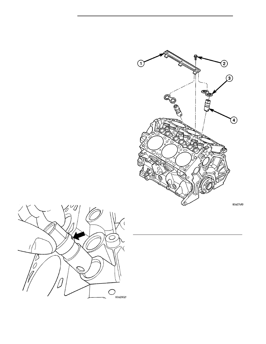
(2) Remove the yoke retainer and aligning yokes

(Fig. 47).

(3) Remove the hydraulic lifters. If necessary use

Special Tool C-4129, or equivalent to remove lifters
from bores. If lifters are to be reused, identify each
lifter to ensure installation in original location.

INSTALLATION

(1) Lubricate the lifters with engine oil.

NOTE: Position the lifter in bore with the lubrication
hole facing upward (Fig. 46).

(2) Install the hydraulic lifters with the lubrication

hole facing upward towards middle of block (Fig. 46).
Install lifters in original positions, if reused.

(3) Install lifter aligning yokes (Fig. 47).
(4) Install yoke retainer and torque screws to 12

N·m (105 in. lbs.) (Fig. 47).

(5) Install the cylinder heads. (Refer to 9 -

ENGINE/CYLINDER HEAD - INSTALLATION)

(6) Start and operate engine. Warm up to normal

operating temperature.

CAUTION: To prevent damage to valve mechanism,
engine must not be run above fast idle until all
hydraulic lifters have filled with oil and have
become quiet.

Fig. 46 LIFTER LUBRICATION HOLE

Fig. 47 Lifter Aligning Yoke and Retainer

1 - YOKE RETAINER
2 - BOLT - YOKE RETAINER
3 - ALIGNING YOKE
4 - HYDRAULIC LIFTER

9 - 114

ENGINE 3.3/3.8L

RS

HYDRAULIC LIFTERS (CAM IN BLOCK) (Continued)

CAMSHAFT & BEARINGS (IN
BLOCK)

DESCRIPTION

The nodular iron camshaft is mounted in the

engine block and supported with four steel backed
aluminum bearings (Fig. 48). A thrust plate, located
in front of the first bearing, is bolted to the block and
controls the camshaft end play (Fig. 48). To distin-
guish camshafts between the 3.3L and 3.8L engines,
a cast-in ring is located between the rear bearing
journal and rear lobe (Fig. 49). The 3.3L engine
application is as-cast only. The 3.8L engine applica-
tion the cast ring is machined off.

OPERATION

The camshaft is driven by the crankshaft through

a timing chain and sprockets. The camshaft has pre-
cisely machined (egg-shaped) lobes to provide accu-
rate valve timing and duration.

REMOVAL

(1) Remove the engine assembly from vehicle

(Refer to 9 - ENGINE - REMOVAL).

(2) Remove the cylinder heads (Refer to 9 -

ENGINE/CYLINDER HEAD - REMOVAL).

(3) Remove

the

timing

chain

and

camshaft

sprocket (Refer to 9 - ENGINE/VALVE TIMING/TIM-
ING BELT/CHAIN AND SPROCKETS - REMOVAL).

(4) Remove the hydraulic lifters (Refer to 9 -

ENGINE/ENGINE BLOCK/HYDRAULIC LIFTERS
(CAM IN BLOCK) - REMOVAL). Identify each tappet
for reinstallation in original location.

(5) Remove camshaft thrust plate (Fig. 48).
(6) Install a long bolt into front of camshaft to

facilitate removal of the camshaft.

(7) Remove the camshaft (Fig. 48), being careful

not to damage cam bearings with the cam lobes.

NOTE: The camshaft bearings are serviced with the
engine block.

INSPECTION

(1) Check the cam lobes and bearing surfaces for

abnormal wear and damage (Fig. 50). Replace cam-
shaft as required.

NOTE: If camshaft is replaced due to lobe wear or
damage, always replace the lifters.

(2) Measure the lobe actual wear (unworn area -

wear zone = actual wear) (Fig. 50) and replace cam-
shaft if out of limit. Standard value is 0.0254 mm
(0.001 in.), wear limit is 0.254 mm (0.010 in.).

INSTALLATION

(1) Lubricate camshaft lobes and camshaft bearing

journals with engine oil.

(2) Install a long bolt into the camshaft to assist in

the installation of the camshaft.

(3) Carefully install the camshaft in engine block.
(4) Install camshaft thrust plate and bolts (Fig.

48). Tighten to 12 N·m (105 in. lbs.) torque.

(5) Measure camshaft end play. (Refer to 9 -

ENGINE - SPECIFICATIONS) If not within specifi-
cations, replace thrust plate.

(6) Install the timing chain and sprockets. (Refer

to 9 - ENGINE/VALVE TIMING/TIMING BELT/
CHAIN AND SPROCKETS - INSTALLATION)

Fig. 48 CAMSHAFT AND BEARINGS

1 - CAMSHAFT
2 - THRUST PLATE
3 - BOLT
4 - CAMSHAFT BEARINGS (SERVICED WITH BLOCK)

Fig. 49 CAMSHAFT IDENTIFICATION

1 - CAMSHAFT - 3.3L ENGINE
2 - CAST-IN RING
3 - CAMSHAFT - 3.8L ENGINE
4 - MACHINED CAST-IN RING

RS

ENGINE 3.3/3.8L

9 - 115

NOTE: When camshaft is replaced, all of the
hydraulic lifters must be replaced also.

(7) Install the hydraulic lifters (Refer to 9 -

ENGINE/ENGINE BLOCK/HYDRAULIC LIFTERS
(CAM IN BLOCK) - INSTALLATION). Each lifter
reused must be installed in the same position from
which it was removed.

(8) Install the timing chain cover. (Refer to 9 -

ENGINE/VALVE TIMING/TIMING BELT / CHAIN
COVER(S) - INSTALLATION)

(9) Install the cylinder heads. (Refer to 9 -

ENGINE/CYLINDER HEAD - INSTALLATION)

(10) Install the cylinder head covers. (Refer to 9 -

ENGINE/CYLINDER

HEAD/CYLINDER

HEAD

COVER(S) - INSTALLATION)

(11) Install the lower and upper intake manifolds.

(Refer to 9 - ENGINE/MANIFOLDS/INTAKE MANI-
FOLD - INSTALLATION)

(12) Install the engine assembly. (Refer to 9 -

ENGINE - INSTALLATION)

PISTON & CONNECTING ROD

DESCRIPTION

The pistons are made of cast aluminum alloy and

are a strutless, short skirt design. The piston rings
consist of two compression rings and a three piece oil
ring. Piston pins connect the piston to the forged
steel connecting rods. The piston pins are a press fit
into the connecting rod.

STANDARD PROCEDURE

STANDARD PROCEDURE - FITTING
CONNECTING RODS

The bearing caps are not interchangeable or

reversible, and should be marked at removal to
ensure correct reassembly. The bearing shells must
be

installed

with

the

tangs

inserted

into

the

machined grooves in the rods and caps. Install cap
with the tangs on the same side as the rod. For con-
necting rod bearing fitting (Refer to 9 - ENGINE/EN-
GINE BLOCK/CONNECTING ROD BEARINGS -
STANDARD PROCEDURE). Fit all connecting rods
on one bank until complete.

NOTE: The connecting rod cap bolts should be
examined before reuse. Bolt stretch can be checked
by holding a scale or straight edge against the
threads. If all the threads do not contact the scale
the bolt must be replaced (Fig. 51).

Fig. 50 Checking Camshaft for Wear (Typical)

1 - UNWORN AREA
2 - ACTUAL WEAR
3 - BEARING JOURNAL
4 - LOBE
5 - WEAR ZONE

Fig. 51 Check for Stretched (Necked) Bolts

1 - STRETCHED BOLT
2 - THREADS ARE NOT STRAIGHT ON LINE
3 - THREADS ARE STRAIGHT ON LINE
4 - UNSTRETCHED BOLT

9 - 116

ENGINE 3.3/3.8L

RS

CAMSHAFT & BEARINGS (IN BLOCK) (Continued)

(1) Before installing the nuts the threads should

be oiled with engine oil.

(2) Install nuts finger tight on each bolt then alter-

nately torque each nut to assemble the cap properly.

(3) Tighten the nuts to 54 N·m PLUS 1/4 turn (40

ft. lbs. PLUS 1/4 turn).

(4) Using a feeler gauge, check connecting rod side

clearance (Fig. 52). Refer to Engine Specifications
(Refer to 9 - ENGINE - SPECIFICATIONS).

STANDARD PROCEDURE - FITTING PISTONS

The piston and cylinder wall must be clean and

dry. Piston diameter should be measured 90 degrees
to piston pin at size location shown in (Fig. 53). Cyl-
inder bores should be measured halfway down the
cylinder bore and transverse to the engine crankshaft
center line shown in (Fig. 54). Refer to Engine Spec-
ifications (Refer to 9 - ENGINE - SPECIFICA-
TIONS). Pistons and cylinder bores should be
measured at normal room temperature, 21°C
(70°F).

REMOVAL

(1) Disconnect negative cable from battery.
(2) Remove the cylinder heads. (Refer to 9 -

ENGINE/CYLINDER HEAD - REMOVAL)

(3) Remove the oil pan. (Refer to 9 - ENGINE/LU-

BRICATION/OIL PAN - REMOVAL)

(4) Remove the top ridge of cylinder bores with a

reliable ridge reamer, if necessary, before removing
pistons from cylinder block. Be sure to keep tops
of pistons covered during this operation. Pis-
tons and connecting rods must be removed
from top of cylinder block. When removing pis-
ton and connecting rod assemblies from the
engine, rotate crankshaft so that each connect-
ing rod is centered in cylinder bore.

(5) Inspect connecting rods and connecting rod

caps for cylinder identification. Identify them, if nec-
essary (Fig. 55).

Fig. 52 Checking Connecting Rod Side Clearance

Fig. 53 Piston Measurement Locations

1 - 39.8 mm (1.56 in. ) 3.3L ENGINE
2 - 33.0 mm (1.29 in.) 3.8L ENGINE

Fig. 54 Checking Cylinder Bore Size

Fig. 55 Identify Connecting Rod to Cylinder

1 - CYLINDER NUMBER

RS

ENGINE 3.3/3.8L

9 - 117

PISTON & CONNECTING ROD (Continued)


Content   ..  322  323  324  325   ..