Chrysler Town, Dodge Caravan. Manual - part 309


  Index      Chrysler     Chrysler TOWN & COUNTRY, VOYAGER, Dodge Caravan - service repair manual 2001-2007 year


Search            


Content   ..  307  308  309  310   ..


Chrysler Town, Dodge Caravan. Manual - part 309


OIL PAN

REMOVAL

(1) Raise vehicle on hoist and drain engine oil.
(2) Remove

structural

collar.

(Refer

to

9

-

ENGINE/ENGINE BLOCK/STRUCTURAL COVER -
REMOVAL)

(3) Remove air conditioning compressor bracket to

oil pan bolt.

(4) Remove bolts attaching oil pan.
(5) Remove oil pan.
(6) Clean oil pan and all gasket surfaces.

INSTALLATION

(1)

Apply Mopar

t Engine RTV GEN II at the oil

pump to engine block parting line (Fig. 88).

(2) Install the oil pan gasket to the block.
(3) Install pan and tighten the screws to 12 N·m

(105 in. lbs.).

(4) Install air conditioning compressor bracket to

oil pan bolt.

(5) Install structural collar. (Refer to 9 - ENGINE/

ENGINE BLOCK/STRUCTURAL COVER - INSTAL-
LATION)

(6) Lower vehicle and fill engine crankcase with

proper oil to correct level.

OIL PRESSURE SWITCH

REMOVAL

(1) Raise vehicle.
(2) Position oil collecting container under pressure

switch location.

(3) Disconnect oil pressure switch electrical con-

nector and remove switch (Fig. 89).

INSTALLATION

(1) Install oil pressure switch. Torque switch to 21

N·m (190 in. lbs.) (Fig. 89).

(2) Connect electrical connector
(3) Lower vehicle.
(4) Start engine and allow to run a minimum of 2

minutes.

(5) Shut engine off and check engine oil level.

Adjust level as necessary.
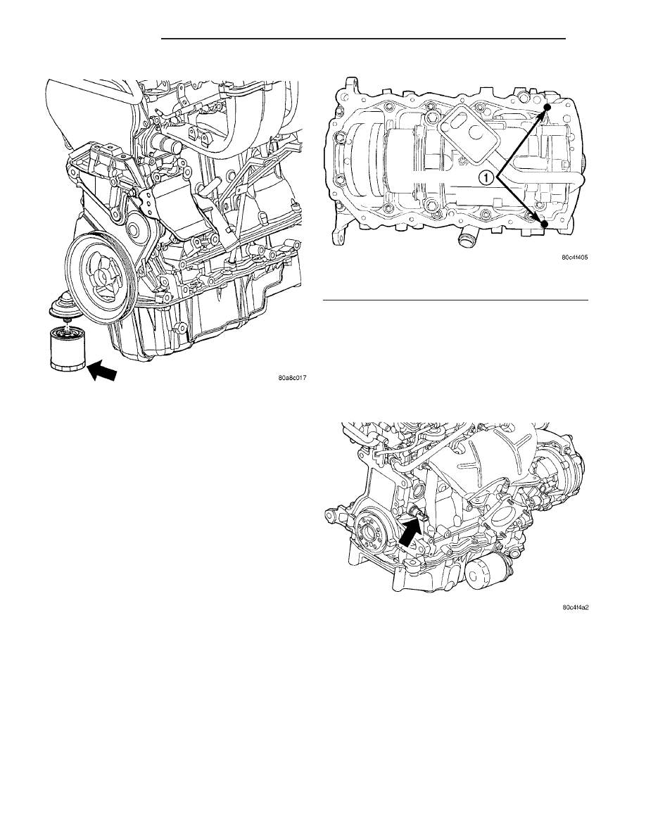
Fig. 87 Oil Filter

Fig. 88 Oil Pan Sealing - Typical

1 - SEALER LOCATIONS

Fig. 89 Engine Oil Pressure Switch

9 - 54

ENGINE 2.4L

RS

OIL FILTER (Continued)

OIL PUMP

REMOVAL

(1) Disconnect negative cable from battery.
(2) Remove timing belt (Refer to 9 - ENGINE/

VALVE TIMING/TIMING BELT AND SPROCKETS -
REMOVAL).

(3) Remove timing belt rear cover (Refer to 9 -

ENGINE/VALVE TIMING/TIMING BELT COVER(S)
- REMOVAL).

(4) Remove oil pan (Refer to 9 - ENGINE/LUBRI-

CATION/OIL PAN - REMOVAL).

(5) Remove

crankshaft

sprocket

using

Special

Tools 6793 and C-4685-C2 (Fig. 90).

(6) Remove crankshaft key (Fig. 91).

(7) Remove oil pick-up tube.

(8) Remove oil pump (Fig. 92) and front crankshaft

seal.

DISASSEMBLY

(1)

To remove the relief valve, proceed as follows:

(a) Remove the threaded plug and gasket from

the oil pump (Fig. 93) .

(b) Remove spring and relief valve (Fig. 93) .

Fig. 90 Crankshaft Sprocket - Removal

1 - SPECIAL TOOL 6793
2 - SPECIAL TOOL C-4685–C2
3 - CRANKSHAFT SPROCKET

Fig. 91 Crankshaft Key

1 - CRANKSHAFT KEY

Fig. 92 Oil Pump

1 - BOLTS
2 - BOLTS
3 - OIL PUMP

Fig. 93 Oil Pressure Relief Valve

1 - PLUG
2 - OIL PUMP BODY
3 - RELIEF VALVE
4 - SPRING
5 - SEAL

RS

ENGINE 2.4L

9 - 55

(2)

Remove oil pump cover fasteners, and lift off

cover (Fig. 94) .

(3)

Remove pump rotors (Fig. 94) .

(4)

Wash all parts in a suitable solvent and

inspect carefully for damage or wear.

CLEANING

(1) Clean all parts thoroughly in a suitable sol-

vent.

INSPECTION

(1) Inspect the mating surfaces of the oil pump

cover. Surface should be smooth. Replace pump cover
if scratched or grooved.

(2) Lay a straightedge across the pump cover sur-

face (Fig. 95). If a 0.025 mm (0.001 in.) feeler gauge
can be inserted between cover and straight edge,
cover should be replaced.

(3) Measure thickness and diameter of outer rotor.

If outer rotor thickness measures 9.40 mm (0.370 in.)
or less (Fig. 96), or if the diameter is 79.95 mm
(3.148 in.) or less, replace outer rotor.

(4) If inner rotor measures 9.40 mm (0.370 in.) or

less replace inner rotor (Fig. 97).

ASSEMBLY

(1) Assemble pump, using new parts as required.

Install the inner rotor with chamfer facing the
cast iron oil pump cover.

(2)

Prime oil pump before installation by filling

rotor cavity with engine oil.

(3)

Install cover and tighten fasteners to 12 N·m

(105 in. lbs.) (Fig. 94).

Fig. 94 Oil Pump

1 - O-RING
2 - SEAL
3 - INNER ROTOR
4 - OIL PUMP COVER
5 - FASTENER
6 - OUTER ROTOR
7 - OIL PUMP BODY

Fig. 95 Checking Oil Pump Cover Flatness

1 - STRAIGHT EDGE
2 - FEELER GAUGE
3 - OIL PUMP COVER

Fig. 96 Measuring Outer Rotor Thickness

Fig. 97 Measuring Inner Rotor Thickness

9 - 56

ENGINE 2.4L

RS

OIL PUMP (Continued)

CAUTION: Oil pump pressure relief valve must be
installed as shown in (Fig. 93) or serious engine
damage may occur.

(4)

Install relief valve, spring, gasket and cap as

shown in (Fig. 93). Tighten cap to 41 N·m (30 ft.
lbs.).

INSTALLATION

(1) Make sure all surfaces are clean and free of oil

and dirt.

(2) Apply Mopar

t Gasket Maker to oil pump as

shown in (Fig. 98). Install O-ring into oil pump body
discharge passage.

(3) Prime oil pump with engine oil before installa-

tion.

(4) Align oil pump rotor flats with flats on crank-

shaft. Install the oil pump to the block (Fig. 92).

CAUTION: To align, the front crankshaft seal MUST
be out of pump, or damage may result.

(5) Install new front crankshaft seal using Special

Tool 6780 (Fig. 99).

(6) Install crankshaft key (Fig. 91).

CAUTION: The crankshaft sprocket is set to a pre-
determined depth from the factory for correct tim-
ing belt tracking. If removed, use of Special Tool
6792 is required to set the sprocket to original
installation depth. An incorrectly installed sprocket
will result in timing belt and engine damage.

(7) Install crankshaft sprocket using Special Tool

6792 (Fig. 100).

(8) Install oil pump pick-up tube.
(9) Install oil pan (Refer to 9 - ENGINE/LUBRI-

CATION/OIL PAN - INSTALLATION).

(10) Install timing belt rear cover (Refer to 9 -

ENGINE/VALVE TIMING/TIMING BELT COVER(S)
- INSTALLATION).

(11) Install timing belt (Refer to 9 - ENGINE/

VALVE TIMING/TIMING BELT AND SPROCKETS -
INSTALLATION).

Fig. 98 Oil Pump Sealing

1 - O-RING
2 - SEALER LOCATION

Fig. 99 Front Crankshaft Seal - Installation

1 - PROTECTOR
2 - SEAL
3 - SPECIAL TOOL 6780

Fig. 100 Crankshaft Sprocket - Installation

1 - SPECIAL TOOL 6792
2 - TIGHTEN NUT TO INSTALL

RS

ENGINE 2.4L

9 - 57

OIL PUMP (Continued)


Content   ..  307  308  309  310   ..