Chrysler Town, Dodge Caravan. Manual - part 123


  Index      Chrysler     Chrysler TOWN & COUNTRY, VOYAGER, Dodge Caravan - service repair manual 2001-2007 year


Search            


Content   ..  121  122  123  124   ..


Chrysler Town, Dodge Caravan. Manual - part 123


LOWER DRIVE UNIT TRACK &
RACK

DESCRIPTION

Vehicles equipped with a power sliding side door

utilize a lower drive unit track or door track and
rack assembly. This track provides a mating rack
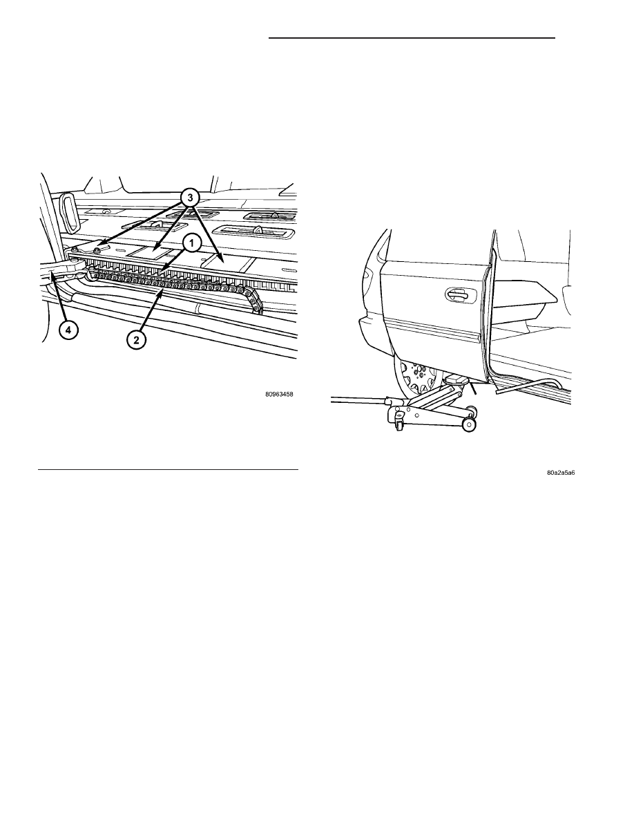
gear (Fig. 13) for the lower drive unit to engage. The
track also accepts the lower hinge rollers, which
helps support the weight of the side door as well as
providing a smooth surface for the hinge rollers to
move upon.

The lower door track is a replaceable component.

Consult your Mopar parts catalog for specific part
numbers.

OPERATION

With the start of a power door open cycle, the door

motor drives the flex drive assembly. The flex drive
assembly drives the lower drive unit. A metal drive
gear which is part of the lower drive unit, meshes
with the door track rack teeth and moves the door
into the full open position. The same operation
repeats itself, during a power close cycle only the sys-
tem rotates in the opposite direction.

REMOVAL

(1) Disconnect and isolate the negative battery

cable.

(2) Remove the side door sill plate from the lower

of the door opening. Refer to the Body section for the
procedure.

(3) Remove the hold-open striker. Refer to Body for

the procedure.

(4) Position a floor jack, with a block of wood

under the leading edge of the side door to support it
(Fig. 14).

(5) Remove the lower hinge assembly from the

door. Refer to the Body section of the service manual
for the procedure.

(6) Position the wire harness assembly out of door

opening, this will allow sufficient room to remove the
door track.

(7) Pull back the sealing patches and remove the

lower track retaining nuts (Fig. 15).

(8) Carefully remove the lower door track from the

vehicle.

INSTALLATION

(1) Carefully position the lower door track in the

vehicle.

(2) Install the lower track retaining nuts and

install the sealing patches. Torque the nuts to 70 in.
lbs.

(3) Install the lower hinge assembly on the door.

Refer to the Body section of the service manual for
the procedure.

Fig. 13 Rack Access Hole Locations

1 - Lower Door Track and Rack Assembly
2 - Wire Harness
3 - Rack Access Hole Sealing Patches
4 - Lower Drive Unit Cover

Fig. 14 Supporting Side Door

8N - 34

POWER SLIDING DOOR SYSTEM

RS

NOTE: Take care to locate the lower hinge assem-
bly on the door in its original position (ie. match
screw washer with rings left on hinge). Adjust door
fit if required.

(4) Remove the floor jack.
(5) Install the hold-open striker. Refer to the Body

section for the procedure.

(6) Install the side door sill plate on the lower of

the door opening. Refer to the Body section for the
procedure.

(7) Connect the negative battery cable.

WIRING HARNESS

DESCRIPTION

The wire harness supplies power (12v), ground and

various electrical signals to the side sliding door for
various power door functions. A plastic chain or wir-
ing track covers the wire harness assembly (Fig. 16)
and is used to protect the wire harness from abrasion
and/or tangling. This wiring track is replaced with
the wire harness assembly.

The wire harness assembly is a replaceable compo-

nent. Consult your Mopar parts catalog for specific
part numbers.

OPERATION

The wire harness and plastic wiring track provide

a safe and reliable means of supplying power, ground

and other various electrical connections to the side
sliding door. During sliding door movement the wir-
ing track folds and unfolds like the links in a chain.

REMOVAL

(1) Disconnect and isolate the negative battery

cable.

(2) Remove the appropriate door trim panel from

the sliding side door. Refer to the Body section for
the procedure.

(3) Remove the lower drive unit cover retaining

screws and remove the cover (Fig. 17).

(4) Disconnect the power side door electrical con-

nector, located just behind the lower drive unit
assembly.

(5) Disengage retaining pushpin and pull wire har-

ness away from its power side door mounting loca-
tion (Fig. 16).

(6) Using a flat bladed screwdriver, unsnap the

wire harness retaining clip from the lower drive unit.

(7) Slide the wire harness off the forward lower

drive unit stud.

(8) Using a pushpin removal tool, unsnap wire

harness retaining pushpins from the rocker panel.

(9) Remove side door lower sill plate. Refer to

Body for the procedure.

(10) Pull back the rearward edge of the B-pillar

trim to access the wire harness connector and discon-
nect connector.

Fig. 15 Lower Track Retaining Nuts

1 - Lower Track Retaining Nuts
2 - Lower Door Track

Fig. 16 Wire Harness Position and Orientation

1 - Lower Door Track and Rack Assembly
2 - Wire Harness
3 - Rack Access Hole Sealing Patches
4 - Lower Drive Unit Cover

RS

POWER SLIDING DOOR SYSTEM

8N - 35

LOWER DRIVE UNIT TRACK & RACK (Continued)

(11) Remove the wire harness assembly from the

vehicle.

INSTALLATION

(1) Position the wire harness assembly in the vehi-

cle.

(2) Connect the wire harness connector located at

the rearward edge of the B-pillar.

(3) Install the side door lower sill plate. Refer to

the Body section for the procedure.

(4) Snap the wire harness retaining pushpins in

the rocker panel.

(5) Slide the wire harness on the lower drive unit

stud.

(6) Install the wire harness retaining clip on the

lower drive unit stud.

(7) Connect the power side door electrical connec-

tor, located just behind the lower drive unit.

(8) Install the lower drive unit cover and retaining

screws.

(9) Install the appropriate door trim panel on the

sliding side door. Refer to the Body section for the
procedure.

(10) Connect the negative battery cable.

FLEX DRIVE

DESCRIPTION

Vehicles equipped with a power sliding side door

utilize a flex drive assembly. The flex drive assembly
is located in the lower portion of the door (Fig. 18)
and is used to connect the door motor to the lower
drive unit. An E-clip is used to secure the flexdrive to
the motor assembly, while the flex drive collar is
used to secure the drive to the lower drive unit. The
flex drive assembly is basically a flexible drive shaft
for the power side door system.

The flex drive assembly is a replaceable compo-

nent. Consult your Mopar parts catalog for specific
part numbers.

OPERATION

With one end of the flex drive attached to the door

motor and the other attached to the lower drive unit,
the flex drive transfers the power and torque from
the motor to the drive unit. A square shaped drive
cable, inside the flex drive assembly engages the
motor drive and rotates to move the door accordingly.

Fig. 17 Lower Hinge/Drive Assembly

1 - Lower Drive Unit Cover
2 - Lower Drive Unit Cover Retaining Screws
3 - Sliding Door
4 - Lower Hinge Arm Bracket

Fig. 18 Side Door Components

1 - Sliding Door Control Module
2 - Module Retaining Screw
3 - Module Electrical Connectors
4 - Door Motor Assembly
5 - Flex Drive Assembly
6 - Door Motor Retaining Fasteners
7 - Door Motor Electrical Connector

8N - 36

POWER SLIDING DOOR SYSTEM

RS

WIRING HARNESS (Continued)

REMOVAL

(1) Disconnect and isolate the negative cable.
(2) Remove the side door trim panel from the vehi-

cle. Refer to the Body section for the procedure.

(3) Remove the weathershield. Refer to the Body

section for the procedure.

(4) Remove the E-clip from the flex drive assembly

(Fig. 19).

(5) Pull the flex drive straight out of the motor

assembly.

(6) Remove the lower drive unit cover retaining

screws and remove the cover (Fig. 20).

(7) Expand the flex drive collar, next to the lower

drive unit until the flex drive can be pulled straight
off the lower drive unit.

(8) Remove the flex drive assembly from the vehicle.

INSTALLATION

(1) Position the flex drive assembly in the vehicle.
(2) Install the flex drive on the lower drive unit.

Push straight on until it snaps in place. It may be
necessary to rotate drive unit gear slightly until the
flex drive seats in place.

(3) Install the lower drive unit cover and retaining

screws.

(4) Install the flex drive in the motor assembly.

Line up the square shaped inner shaft and push
straight on (Fig. 21).

(5) Install the E-clip on the flex drive assembly

(Fig. 19).

(6) Install the weathershield. Refer to Body for the

procedure.

(7) Install the side door trim panel on the vehicle.

Refer to Body for the procedure.

(8) Connect the negative cable.

Fig. 19 Flex Drive E-Clip

1 - Flex Drive Cable Retaining Clip
2 - Flex Drive Cable
3 - Side Door Motor Assembly

Fig. 20 Lower Hinge/Drive Assembly

1 - Lower Drive Unit Cover
2 - Lower Drive Unit Cover Retaining Screws
3 - Sliding Door
4 - Lower Hinge Arm Bracket

Fig. 21 Flex Drive Cable

1 - Door Motor
2 - Flex Drive Collar
3 - Flex Drive Inner Shaft

RS

POWER SLIDING DOOR SYSTEM

8N - 37

FLEX DRIVE (Continued)


Content   ..  121  122  123  124   ..