Chrysler Town, Dodge Caravan. Manual - part 98


  Index      Chrysler     Chrysler TOWN & COUNTRY, VOYAGER, Dodge Caravan - service repair manual 2001-2007 year


Search            


Content   ..  96  97  98  99   ..


Chrysler Town, Dodge Caravan. Manual - part 98


(4) Reconnect the instrument panel switch bank

and test the heated seat system for proper operation.
If the system is still inoperative proceed with check-
ing remaining components.

REMOVAL

WARNING: ON VEHICLES EQUIPPED WITH AIR-
BAGS, REFER TO THE RESTRAINTS SECTION OF
THIS MANUAL BEFORE ATTEMPTING ANY STEER-
ING

WHEEL,

STEERING

COLUMN,

SEAT

OR

INSTRUMENT PANEL COMPONENT DIAGNOSIS OR
SERVICE. FAILURE TO TAKE THE PROPER PRE-
CAUTIONS COULD RESULT IN ACCIDENTAL AIR-
BAG DEPLOYMENT AND POSSIBLE PERSONAL
INJURY.

(1) Disconnect and isolate the battery negative

cable.

(2) Remove the instrument panel center bezel.

Refer to Instrument Panel Center Bezel in the
Body section for the procedure.

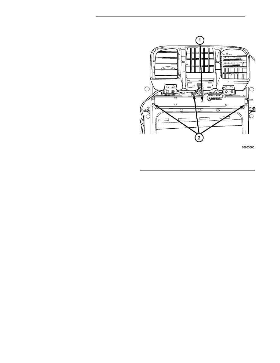
(3) Remove the three screws (Fig. 8) that secure

the heated seat switch to the back of the instrument
panel center bezel.

(4) Remove the heated seat switch from the back

of the instrument panel center bezel.

INSTALLATION

(1) Position the heated seat switch onto the back

of the instrument panel center bezel.

(2) Install and tighten the three screws that secure

the heated seat switch to the back of the instrument

panel center bezel (Fig. 8). Tighten the screws to 1.5
N·m (13 in. lbs.).

(3) Install the center bezel onto the instrument

panel. Refer to Instrument Panel Center Bezel in
the Body section for the procedure.

(4) Reconnect the battery negative cable.

Fig. 8 SWITCH RETAINING SCREWS

1 - HEATED SEAT SWITCH ASSEMBLY
2 - RETAINING SCREWS

8G - 14

HEATED SEAT SYSTEM

RS

PASSENGER HEATED SEAT SWITCH (Continued)

HORN

TABLE OF CONTENTS

page

page

HORN SYSTEM

DESCRIPTION

. . . . . . . . . . . . . . . . . . . . . . . . . . 1

OPERATION

. . . . . . . . . . . . . . . . . . . . . . . . . . . . 1

DIAGNOSIS AND TESTING - HORN SYSTEM

. . . 1

HORN

DIAGNOSIS AND TESTING - HORN

. . . . . . . . . . 3

REMOVAL

. . . . . . . . . . . . . . . . . . . . . . . . . . . . . 5

INSTALLATION

. . . . . . . . . . . . . . . . . . . . . . . . . . 5

HORN RELAY

DIAGNOSIS AND TESTING - HORN RELAY

. . . . 5

REMOVAL

. . . . . . . . . . . . . . . . . . . . . . . . . . . . . 5

INSTALLATION

. . . . . . . . . . . . . . . . . . . . . . . . . . 5

HORN SWITCH

DESCRIPTION

. . . . . . . . . . . . . . . . . . . . . . . . . . 5

HORN SYSTEM

DESCRIPTION

WARNING: ON VEHICLES EQUIPPED WITH AIR-
BAG, REFER TO ELECTRICAL, RESTRAINTS FOR
SAFETY PRECAUTIONS. DISCONNECT THE NEGA-
TIVE CABLE FROM THE BATTERY BEFORE SER-
VICING COMPONENTS INVOLVING THE AIRBAG
SYSTEM. ACCIDENTAL DEPLOYMENT OF AIRBAG
AND PERSONAL INJURY CAN RESULT.

The horn circuit consists of a horn switch, clock-

spring, horn relay, horns and Integrated Power Mod-
ule (IPM). The horn switch is a membrane switch
located in the airbag trim cover. The horns are
located forward of the left front wheel behind the
bumper fascia.

OPERATION

The horn relay plugs into the Integrated Power

Module (IPM) which is located in the engine com-
partment. For circuit information and component
locations, refer to the appropriate wiring information.
The wiring information includes wiring diagrams,
proper wire and connector repair procedures, details
of wire harness routing and retention, connector pin-
out information and location views for the various
wire harness connectors, splices and grounds.

The horns will not function if the switch is

“CLOSED” for more than 30 seconds. Once the
switch is “OPEN”, a 20–30 second delay will occur
before the horns are functional again.

DIAGNOSIS AND TESTING - HORN SYSTEM

WARNING: ON VEHICLES EQUIPPED WITH AIR-
BAGS,

REFER

TO

ELECTRICAL,

RESTRAINTS

BEFORE ATTEMPTING ANY STEERING WHEEL,
STEERING

COLUMN,

OR

INSTRUMENT

PANEL

COMPONENT DIAGNOSIS OR SERVICE. FAILURE
TO TAKE THE PROPER PRECAUTIONS COULD
RESULT IN ACCIDENTAL AIRBAG DEPLOYMENT
AND POSSIBLE PERSONAL INJURY.

Refer to Horn System Test below. If the horn does

not sound, check horn fuse located in the Integrated
Power Module (IPM). If the fuse is blown, replace
with the correct fuse. If the horns fail to sound and
the new fuse blows when depressing the horn switch,
a short circuit in the horn or the horn wiring
between the fuse terminal and the horn is responsi-
ble, or a defective horn switch allowed the horn to
burn out is responsible.

If the fuse is OK, test horn relay (Refer to 8 -

ELECTRICAL/HORN/HORN RELAY - DIAGNOSIS
AND TESTING).

If the relay is OK, test horn. Refer to Horn System

Test.

CAUTION: Continuous sounding of horn may

cause horn failure.

Should the horn sound continuously:
• Unplug the horn relay from IPM.

• Refer to (Refer to 8 - ELECTRICAL/HORN/

HORN RELAY - DIAGNOSIS AND TESTING).

Refer to the appropriate wiring information. The

wiring information includes wiring diagrams, proper
wire and connector repair procedures, details of wire
harness routing and retention, connector pin-out
information and location views for the various wire
harness connectors, splices and grounds.

RS

HORN

8H - 1

HORN SYSTEM TEST

CONDITION

POSSIBLE CAUSE

CORRECTION

HORN SOUNDS CONTINUOUSLY.
NOTE: IMMEDIATELY UNPLUG HORN
RELAY IN THE IPM.

(1) FAULTY HORN RELAY.

(1) REFER TO HORN RELAY TEST.

(2) HORN CONTROL
CIRCUIT TO RELAY
SHORTED TO GROUND.

(2) CHECK TERMINAL 85 IN IPM
FOR CONTINUITY TO GROUND. IF
CONTINUITY TO GROUND
INDICATES:
(A) STEERING WHEEL HORN
SWITCH/LEAD SHORTED TO
GROUND.
(B) WIRING HARNESS SHORTED
TO GROUND. FIND THE SHORT
AND REPAIR AS NECESSARY.

(3) PINCHED HORN
SWITCH WIRE UNDER
DRIVER AIRBAG MODULE.

(3) REPLACE DRIVER AIRBAG
MODULE TRIM COVER.

(4) FAULTY HORN SWITCH.

(4) REPLACE DRIVER AIRBAG
MODULE TRIM COVER.

(5) FAULTY CLOCKSPRING.

(5) REPLACE CLOCKSPRING.

(6) FAULTY FRONT
CONTROL MODULE.

(6) REFER TO ELECTRONIC
CONTROL MODULES/FRONT
CONTROL MODULE.

HORN SOUND INTERMITTENTLY AS
THE STEERING WHEEL IS TURNED.

(1) HORN RELAY
CONTROL CIRCUIT X3 IS
SHORTED TO GROUND
INSIDE STEERING
COLUMN OR WHEEL.

(1) REMOVE DRIVER AIRBAG
MODULE AND/OR WHEEL. CHECK
FOR RUBBING OR LOOSE
WIRE/CONNECTOR, REPAIR AS
NECESSARY.

(2) PINCHED HORN
SWITCH WIRE UNDER
DRIVER AIRBAG MODULE.

(2) REPLACE DRIVER AIRBAG
MODULE TRIM COVER.

(3) FAULTY HORN SWITCH.

(3) REPLACE DRIVER AIRBAG
MODULE TRIM COVER.

(4) FAULTY CLOCKSPRING.

(4) REPLACE CLOCKSPRING.

8H - 2

HORN

RS

HORN SYSTEM (Continued)

CONDITION

POSSIBLE CAUSE

CORRECTION

HORN DOES NOT SOUND

(1) CHECK FUSE 8 IN
INTELLIGENT POWER
MODULE.

(1) REPLACE FUSE IF BLOWN
REPAIR AS NECESSARY.

(2) NO VOLTAGE AT HORN
RELAY TERMINALS 30 &
86, AND FUSE IS OK.

(2) NO VOLTAGE, REPAIR THE
CIRCUIT AS NECESSARY.

(3) OPEN CIRCUIT FROM
TERMINAL 85 OF THE
HORN RELAY TO HORN
SWITCH, X3 CIRCUIT.

(3) REPAIR CIRCUIT AS
NECESSARY.

(4) FAULTY OR DAMAGED
HORN.

(4) VOLTAGE AT HORN WHEN
HORN SWITCH IS PRESSED,
REPLACE HORN.

(5) FAULTY HORN SWITCH.

(5) REPLACE DRIVER AIRBAG
MODULE TRIM COVER.

(6) FAULTY CLOCKSPRING.

(6) REPLACE CLOCKSPRING.

(7) FAULTY FRONT
CONTROL MODULE.

(7) REFER TO ELECTRONIC
CONTROL MODULES/FRONT
CONTROL MODULE.

FUSE BLOWS WHEN HORN SOUNDS

(1) SHORT CIRCUIT IN
HORN OR HORN WIRING.

(1) REMOVE HORN RELAY, CHECK
FOR SHORTED HORN OR HORN
WIRING. DISCONNECT HORN WIRE
HARNESS TO ISOLATE SHORT
AND REPAIR AS NECESSARY.

(2) FAULTY CLOCKSPRING.

(2) REPLACE CLOCKSPRING.

FUSE BLOWS WITHOUT BLOWING
HORN

(1) SHORT CIRCUIT.

(1) REMOVE RELAY, INSTALL NEW
FUSE, IF FUSE DOES NOT BLOW
REPLACE HORN RELAY. IF FUSE
BLOWS WITH RELAY REMOVED,
CHECK FOR SHORT TO GROUND
WITH OHMMETER ON CIRCUIT
BETWEEN TERMINALS 30 & 86
AND THE FUSE TERMINAL. REPAIR
AS NECESSARY.

(2) FAULTY CLOCKSPRING.

(2) REPLACE CLOCKSPRING.

HORN

DIAGNOSIS AND TESTING - HORN

HORN

(1) Disconnect wire connector at horn.
(2) Using a voltmeter, connect one lead to ground

terminal and the other lead to the positive wire ter-
minal (Fig. 1).

(3) Depress

the

horn

switch,

battery

voltage

should be present.

(4) If no voltage, refer to HORNS WILL NOT

SOUND. If voltage is OK, go to step Step 5.

(5) Using ohmmeter, test ground wire for continu-

ity to ground.

(6) If no ground repair as necessary.
(7) If wires test OK and horn does not sound,

replace horn.

HORNS SOUND CONTINUOUSLY

CAUTION: Continuous sounding of horns may
cause relay to fail.

The horn switch (membrane) sometimes can be the

cause without the switch being depressed.

(1) Remove the horn relay from the intelligent

power module.

RS

HORN

8H - 3

HORN SYSTEM (Continued)


Content   ..  96  97  98  99   ..