Chrysler Town, Dodge Caravan. Manual - part 92


  Index      Chrysler     Chrysler TOWN & COUNTRY, VOYAGER, Dodge Caravan - service repair manual 2001-2007 year


Search            


Content   ..  90  91  92  93   ..


Chrysler Town, Dodge Caravan. Manual - part 92


REMOVAL

(1) Release hood latch and open hood.
(2) Disconnect battery negative cable.
(3) Raise vehicle and support.
(4) Remove the right front lower splash shield.
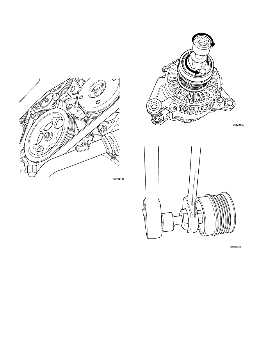
(5) Remove accessory drive belt, refer to the Cool-

ing System section for proper procedures (Fig. 4).

(6) Lower vehicle.
(7) Remove the Air Box, refer to the Engine section

for more information.

(8) Remove the decoupler pulley cover.
(9) Use Special Tool #8433 (Fig. 6) to loosen the

Generator Decoupler (Fig. 5).

(10) Remove the tool.
(11) Remove the Generator Decoupler.

INSTALLATION

(1) Install the Generator Decoupler to the genera-

tor shaft.

(2) Use Special Tool #8433 (Fig. 6) to tighten the

Generator Decoupler (Fig. 7). Refer to the torque
chart for the proper torque.

(3) Install a new decoupler pulley cover.
(4) Install the Air Box, refer to the Engine section

for more information.

(5) Raise vehicle and support.
(6) Install accessory drive belt, refer to the Cooling

System section for proper procedures (Fig. 4).

(7) Install the right front lower splash shield.
(8) Lower vehicle.
(9) Connect battery negative cable.

Fig. 4 DRIVE BELT 3.3/3.8L

Fig. 5 DECOUPLER REMOVAL (LITENS)

Fig. 6 SPECIAL TOOL 8433 AND DECOUPLER

8F - 26

CHARGING

RS

GENERATOR DECOUPLER PULLEY (Continued)

VOLTAGE REGULATOR

DESCRIPTION

The Electronic Voltage Regulator (EVR) is not a

separate component. It is actually a voltage regulat-
ing circuit located within the Powertrain Control
Module (PCM). The EVR is not serviced separately. If
replacement is necessary, the PCM must be replaced.

OPERATION

The amount of DC current produced by the gener-

ator is controlled by EVR circuitry contained within
the PCM. This circuitry is connected in series with
the generators second rotor field terminal and its
ground.

Voltage is regulated by cycling the ground path on

SBEC vehicles or the power side on the NGC vehi-
cles, to control the strength of the rotor magnetic
field. The EVR circuitry monitors system line voltage
at the PDC and calculated battery temperature or
inlet air temperature sensor (refer to Inlet Air Tem-
perature Sensor, if equipped, for more information ).
It then determines a target charging voltage. If
sensed battery voltage is lower than the target volt-
age, the PCM feeds the field winding until sensed
battery voltage is at the target voltage. A circuit in
the PCM cycles the feed side of the generator field at
250 times per second (250Hz), but has the capability
to feed the field control wire 100% of the time (full
field) to achieve the target voltage. If the charging
rate cannot be monitored (limp-in), a duty cycle of
20% is used by the PCM in order to have some gen-
erator output. Also refer to Charging System Opera-
tion for additional information.

Fig. 7 DECOUPLER INSTALLATION (Litens)

RS

CHARGING

8F - 27

GENERATOR DECOUPLER PULLEY (Continued)

STARTING

TABLE OF CONTENTS

page

page

STARTING

DESCRIPTION

. . . . . . . . . . . . . . . . . . . . . . . . . 28

OPERATION

. . . . . . . . . . . . . . . . . . . . . . . . . . . 28

DIAGNOSIS AND TESTING

DIAGNOSIS AND TESTING - STARTING

SYSTEM TEST . . . . . . . . . . . . . . . . . . . . . . . 28

DIAGNOSIS AND TESTING - CONTROL

CIRCUIT TEST . . . . . . . . . . . . . . . . . . . . . . . . 30

DIAGNOSIS AND TESTING - FEED CIRCUIT

RESISTANCE TEST . . . . . . . . . . . . . . . . . . . . 32

DIAGNOSIS AND TESTING - FEED CIRCUIT

TEST . . . . . . . . . . . . . . . . . . . . . . . . . . . . . . . 33

SPECIFICATIONS

Torques

. . . . . . . . . . . . . . . . . . . . . . . . . . . . . 33

STARTER

. . . . . . . . . . . . . . . . . . . . . . . . . . . 34

STARTER MOTOR

REMOVAL

REMOVAL - 2.4L

. . . . . . . . . . . . . . . . . . . . . . 34

REMOVAL - 3.3/3.8L

. . . . . . . . . . . . . . . . . . . 35

INSTALLATION

INSTALLATION - 2.4L

. . . . . . . . . . . . . . . . . . 35

INSTALLATION - 3.3/3.8L

. . . . . . . . . . . . . . . . 36

STARTING

DESCRIPTION

The starting system consists of:
• Starter relay

• Starter motor (including an integral starter sole-

noid)

Other components to be considered as part of start-

ing system are:

• Battery

• Battery cables

• Ignition switch and key lock cylinder

• Clutch pedal position switch (manual transmis-

sion)

• Park/neutral position switch (automatic trans-

mission)

• Wire harnesses and connections.
The Battery, Starting, and Charging systems oper-

ate in conjunction with one another, and must be
tested as a complete system. For correct operation of
starting/charging systems, all components used in
these 3 systems must perform within specifications.
When attempting to diagnose any of these systems, it
is important that you keep their interdependency in
mind.

The diagnostic procedures used in each of these

groups include the most basic conventional diagnostic
methods, to the more sophisticated On-Board Diag-
nostics (OBD) built into the Powertrain Control Mod-
ule (PCM). Use of an induction-type milliampere
ammeter, volt/ohmmeter, battery charger, carbon pile
rheostat (load tester), and 12-volt test lamp may be
required.

OPERATION

These components form two separate circuits. A

high amperage circuit that feeds the starter motor up
to 300+ amps, and a control circuit that operates on
less than 20 amps.

The PCM controls a double start over-ride safety

that does not allow the starter to be engaged if the
engine is already running.

DIAGNOSIS AND TESTING

DIAGNOSIS AND TESTING - STARTING
SYSTEM TEST

For circuit descriptions and diagrams, refer to the

Wiring Diagrams.

WARNING: ON VEHICLES EQUIPPED WITH AIR-
BAGS, REFER TO THE PASSIVE RESTRAINT SYS-
TEMS BEFORE ATTEMPTING STEERING WHEEL,
STEERING

COLUMN,

OR

INSTRUMENT

PANEL

COMPONENT DIAGNOSIS OR SERVICE. FAILURE
TO TAKE THE PROPER PRECAUTIONS COULD
RESULT IN ACCIDENTAL AIRBAG DEPLOYMENT
AND POSSIBLE PERSONAL INJURY.

INSPECTION

Before removing any unit from the starting system

for repair or diagnosis, perform the following inspec-
tions:

• Battery - Visually inspect the battery for indi-

cations of physical damage and loose or corroded
cable connections. Determine the state-of-charge and
cranking capacity of the battery. Charge or replace

8F - 28

STARTING

RS

the battery, if required. Refer to the Battery section
for more information.

• Ignition Switch - Visually inspect the ignition

switch for indications of physical damage and loose
or corroded wire harness connections.

• Transmission Range Sensor or Park/Neu-

tral Switch - Visually inspect the transmission
range sensor for indications of physical damage and
loose or corroded wire harness connections.

• Starter Relay - Visually inspect the starter

relay for indications of physical damage and loose or
corroded wire harness connections.

• Starter Motor - Visually inspect the starter

motor for indications of physical damage and loose or
corroded wire harness connections.

• Starter Solenoid - Visually inspect the starter

solenoid for indications of physical damage and loose
or corroded wire harness connections.

• Wiring - Visually inspect the wire harness for

damage. Repair or replace any faulty wiring, as
required. Check for loose or corroded wire harness
connections at main engine ground and remote jump
post.

• Power Distribution Center (PDC) - Visually

inspect the B+ connections at the PDC for physical
damage and loose or corroded harness connections.

STARTING SYSTEM DIAGNOSIS

CONDITION

POSSIBLE CAUSE

CORRECTION

STARTER FAILS
TO ENGAGE.

1. BATTERY
DISCHARGED OR
FAULTY.

1. REFER TO THE BATTERY SECTION FOR MORE
INFORMATION. CHARGE OR REPLACE BATTERY, IF
REQUIRED.

2. STARTING CIRCUIT
WIRING FAULTY.

2. REFER TO FEED CIRCUIT RESISTANCE TEST AND FEED
CIRCUIT TEST IN THIS SECTION.

3. STARTER RELAY
FAULTY.

3. REFER TO RELAY TEST, IN THIS SECTION. REPLACE
RELAY, IF NECESSARY.

4. IGNITION SWITCH
FAULTY.

4. REFER TO IGNITION SWITCH TEST, IN THE STEERING
SECTION OR 8 WIRING DIAGRAMS. REPLACE SWITCH, IF
NECESSARY.

5. PARK/NEUTRAL
POSITION SWITCH
(AUTO TRANS) FAULTY
OR MIS-ADJUSTED.

5. REFER PARK/NEUTRAL POSITION SWITCH TEST, IN THE
TRANSAXLE. SECTION FOR MORE INFORMATION. REPLACE
SWITCH, IF NECESSARY.

6. CLUTCH INTERLOCK
SWITCH (MAN TRANS)
FAULTY.

6. REFER TO CLUTCH PEDAL POSITION SWITCH TEST, IN
THE CLUTCH. SECTION. REPLACE SWITCH, IF NECESSARY.

7. STARTER SOLENOID
FAULTY.

7. REFER TO SOLENOID TEST, IN THIS SECTION. REPLACE
STARTER ASSEMBLY, IF NECESSARY.

8. STARTER ASSEMBLY
FAULTY.

8. IF ALL OTHER STARTING SYSTEM COMPONENTS AND
CIRCUITS CHECK OK, REPLACE STARTER ASSEMBLY.

9. FAULTY TEETH ON
RING GEAR.

9. ROTATE FLYWHEEL 360°, AND INSPECT TEETH AND RING
GEAR REPLACED IF DAMAGED.

10. PCM DOUBLE
START OVERRIDE
OUTPUT FAILURE.

10. REFER TO PCM DIAGNOSTIC. CHECK FOR CONTINUITY
BETWEEN PCM AND TERMINAL 85. REPAIR OPEN CIRCUIT
AS REQUIRED. IF OK, PCM MAY BE DEFECTIVE.

STARTER
ENGAGES,
FAILS TO TURN
ENGINE.

1. BATTERY
DISCHARGED OR
FAULTY.

1. REFER TO THE BATTERY SECTION FOR MORE
INFORMATION. CHARGE OR REPLACE BATTERY AS
NECESSARY.

RS

STARTING

8F - 29

STARTING (Continued)


Content   ..  90  91  92  93   ..