Chrysler Town, Dodge Caravan. Manual - part 63


  Index      Chrysler     Chrysler TOWN & COUNTRY, VOYAGER, Dodge Caravan - service repair manual 2001-2007 year


Search            


Content   ..  61  62  63  64   ..


Chrysler Town, Dodge Caravan. Manual - part 63


DIAGNOSIS AND TESTING - DRIVE PLATE
MISALIGNMENT

Common causes of misalignment are:
• Heat warping

• Mounting drive plate on a dirty crankshaft

flange

• Incorrect bolt tightening

• Improper seating on the crankshaft shoulder

• Loose crankshaft bolts
Clean the crankshaft flange before mounting the

drive plate. Dirt and grease on the flange surface
may misalign the flywheel, causing excessive runout.
Use new bolts when mounting drive plate to crank-
shaft. Tighten drive plate bolts to specified torque
only. Over-tightening can distort the drive plate hub
causing excessive runout.

DIAGNOSIS AND TESTING - CLUTCH COVER
AND DISC RUNOUT

Check condition of the clutch cover before installa-

tion. A warped cover or diaphragm spring will cause
grab and/or incomplete release or engagement. Use
care when handling the clutch assembly. Impact can
distort the cover, diaphragm spring, and release fin-
gers.

DIAGNOSIS AND TESTING - CLUTCH CHATTER
COMPLAINTS

For all clutch chatter complaints, perform the fol-

lowing:

(1) Check for loose, misaligned, or broken engine

and transmission mounts. If present, they should be
corrected at this time. Test vehicle for chatter. If
chatter is gone, there is no need to go any further.

(2) If chatter persists, check hydraulic clutch

release system is functioning properly.

(3) Check for loose connections in drivetrain. Cor-

rect any problems and determine if clutch chatter
complaints have been satisfied. If not:

(a) Remove transaxle.
(b) Check to see if the release bearing is sticky

or binding. Replace bearing, if needed.

(c) Check linkage for excessive wear on the pivot

stud and fork fingers. Replace all worn parts.

(d) Check clutch assembly for contamination

(dirt, oil). Replace clutch assembly, if required.

(e) Check to see if the clutch disc hub splines

are damaged. Replace with new clutch assembly, if
necessary.

(f) Check

input

shaft

splines

for

damage.

Replace, if necessary.

(g) Check for uneven wear on clutch fingers.
(h) Check for broken clutch cover diaphragm

spring fingers. Replace with new clutch assembly,
if necessary.

SPECIAL TOOLS - T850 TRANSAXLE

CLUTCH RELEASE LEVER AND
BEARING

REMOVAL

(1) Remove transaxle assembly. (Refer to 21 -

TRANSMISSION/TRANSAXLE/MANUAL

-

REMOVAL)

(2) Remove modular clutch assembly from input

shaft (2.4L Gas models only).

(3) Grasp clutch release lever and bearing (Fig. 6)

with both hands and pull outward using moderate
pressure to release lever from pivot ball.

(4) Separate release bearing from lever.

NOTE: Remove release lever pivot ball(s) ONLY if
replacement is necessary.

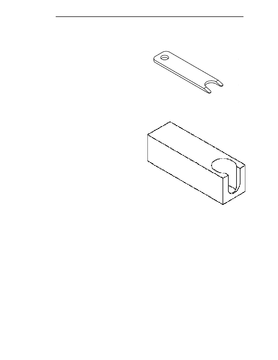
Disconnect Tool, 6638A

Remover/Installer, 6891

6 - 6

CLUTCH

RS

CLUTCH (Continued)

(5) Remove

pivot

ball(s)

using

slide

hammer

C-3752 and remover/installer 6891 (Fig. 7).

INSTALLATION

(1) If removed, install new release lever pivot

ball(s) using slide hammer C-3752 and remover/in-
staller 6891 (Fig. 8) (Fig. 9).

Fig. 6 Release Bearing and Lever

1 - RELEASE LEVER
2 - RELEASE BEARING

Fig. 7 Pivot Ball Removal/Installation

1 - C-3752 SLIDE HAMMER
2 - REMOVER/INSTALLER 6891
3 - PIVOT BALL

Fig. 8 Pivot Ball Removal/Installation

1 - C-3752 SLIDE HAMMER
2 - REMOVER/INSTALLER 6891
3 - PIVOT BALL

Fig. 9 Pivot Ball Position

1 - PIVOT BALL (1)

RS

CLUTCH

6 - 7

CLUTCH RELEASE LEVER AND BEARING (Continued)

(2) Install clutch release bearing to lever. Apply

grease to interface points. Make sure release bearing
retainers engage lever pocket as shown in (Fig. 10).

(3) Apply grease to pivot ball, and on release lever

at slave cylinder contact point.

(4) Install clutch release bearing/lever assembly

into position by sliding bearing onto input bearing
retainer, and using moderate hand pressure to seat
release lever to pivot ball(s) (Fig. 11). A “pop” sound
should be heard. Verify proper engagement by lightly
pulling outward on lever at pivot ball location, and
then actuating lever and bearing to ensure proper
operation.

MASTER CYLINDER - RHD

REMOVAL

(1) Disconnect battery negative cable.
(2) Remove master cylinder to clutch pedal pin

retainer clip. Disengage pushrod from clutch pedal
pin (Fig. 13).

(3) Disengage master cylinder grommet from cowl

panel.

(4) Remove battery and tray.
(5) Diesel models: Remove windshield wiper mod-

ule assembly. (Refer to 8 - ELECTRICAL/WIPERS/
WASHERS/WIPER MODULE - REMOVAL)

(6) Discharge Air Conditioning system. (Refer to 24

- HEATING & AIR CONDITIONING/PLUMBING/
REFRIGERANT - STANDARD PROCEDURE)

(7) Remove suction/discharge line from evaporator

junction block.

(8) Using tool 6638A, disconnect clutch hydraulic

“quick-connect” fitting (Fig. 12).

(9) Remove clutch master cylinder tubing from

retainers in engine compartment.

(10) Remove clutch master cylinder from dash

panel/clutch pedal bracket by rotating 45° clockwise
and pulling outward towards engine (Fig. 13).

(11) Carefully guide clutch master cylinder and

hydraulic plumbing from engine compartment.

Fig. 10 Release Bearing-to-Lever

1 - RETAINER (2)
2 - RELEASE LEVER
3 - RELEASE BEARING

Fig. 11 Release Bearing and Lever

1 - RELEASE LEVER
2 - RELEASE BEARING

Fig. 12 Disconnect Quick-Connect Using Tool 6638A

1 - QUICK CONNECT FITTING
2 - TOOL 6638A

6 - 8

CLUTCH

RS

CLUTCH RELEASE LEVER AND BEARING (Continued)

INSTALLATION

(1) Carefully route master cylinder plumbing into

engine compartment as removed and position master
cylinder to dash panel hole.

(2) Rotate master cylinder 45° clockwise, insert

into dash panel hole, engaging clutch pedal bracket.
Rotate master cylinder 45° counter-clockwise, secur-
ing it to pedal bracket (Fig. 13).

(3) Install and secure grommet to dash panel.
(4) Connect pushrod to clutch pedal pin. Install

retainer clip (Fig. 13).

(5) Secure master cylinder plumbing to retainers

in engine compartment.

(6) Connect clutch master cylinder plumbing to

slave cylinder “quick connect” fitting. An audible
“click” should be heard. Verify connection by pulling
outward.

(7) Connect A/C suction/discharge line to evapora-

tor junction block.

(8) Diesel models: Install wiper module assembly.

(Refer to 8 - ELECTRICAL/WIPERS/WASHERS/
WIPER MODULE - INSTALLATION)

(9) Install battery and tray.
(10) Connect battery negative cable
(11) Charge Air Conditioning system. (Refer to 24 -

HEATING & AIR CONDITIONING/PLUMBING/RE-
FRIGERANT - STANDARD PROCEDURE)

MASTER CYLINDER - LHD

REMOVAL

(1) Disconnect battery cables.
(2) Remove instrument panel lower silencer (Fig.

14).

(3) Remove knee bolster (Fig. 15).

(4) Remove

clutch

master

cylinder

pushrod

retainer clip (Fig. 16).

(5) Disconnect pushrod from clutch pedal (Fig. 16).
(6) Remove battery shield.
(7) Remove battery.
(8) Remove battery tray.
(9) Remove windshield wiper module assembly

(Refer to 8 - ELECTRICAL/WIPERS/WASHERS/
WIPER MODULE - REMOVAL).

Fig. 13 Clutch Master Cylinder at Pedal Bracket

1 - CLUTCH MASTER CYLINDER
2 - RETAINER CLIP
3 - CLUTCH PEDAL PIN
4 - PUSH ROD

Fig. 14 Instrument Panel Lower Silencer

1 - INSTRUMENT PANEL LOWER SILENCER

Fig. 15 Knee Bolster

1 - KNEE BOLSTER

RS

CLUTCH

6 - 9

MASTER CYLINDER - RHD (Continued)


Content   ..  61  62  63  64   ..