Chrysler Town, Dodge Caravan. Manual - part 52
nects the front parking brake cable to the left rear
and intermediate cable. The intermediate cable is
connected to the right rear cable using a parking
brake cable connector.
On vehicles equipped with rear drum brakes, the
rear service brakes also act as the vehicle’s parking
brakes.
Vehicles equipped with rear disc brakes use a
small duo-servo brake assembly mounted to the each
rear disc brake caliper adapter as the parking brake.
The inside of the brake rotor (hat section of drum-in-
hat style brake rotor) is used as the parking brake
drum.
DESCRIPTION - EXPORT
The parking brake system on this vehicle features
a hand-operated parking brake lever. The lever is
located between the two front seats and requires a
special front cable.
OPERATION
The automatic-adjusting feature in the foot oper-
ated parking brake lever continuously applies mini-
mal tension to the parking brake cables when the
parking brake lever is in the released position to
keep them in adjustment at all times. Due to this
feature, the parking brake cables require no periodic
adjustment.
When the parking brake lever is applied, the
cables are pulled, thus applying the brake shoes
(rear drum brakes) or parking brake shoes (rear disc
brakes) at each rear wheel.
The brake shoes are mechanically operated by an
internal lever and strut connected to the rear park-
ing brake cables.
An equalizer bracket is used at the rear end of the
front parking brake cable to distribute tension
equally to each parking brake cable.
STANDARD PROCEDURE
STANDARD PROCEDURE - PARKING BRAKE
AUTOMATIC ADJUSTER TENSION RELEASE
The parking brake lever (pedal) mechanism used
in this vehicle is designed so that the automatic
adjuster is not required to be locked out when servic-
ing the parking brake lever (pedal) or the parking
brake cables.
This parking brake lever (pedal) mechanism is
designed so that the adjuster mechanism will rotate
only half a turn when the tension is released from
the parking brake cable. This eliminates the require-
ment to lock out the automatic adjuster when servic-
ing the parking brake lever (pedal) mechanism and
cables.
Use the following procedure to release the tension
from the parking brake cables and the automatic
adjuster in the parking brake lever (pedal) mecha-
nism.
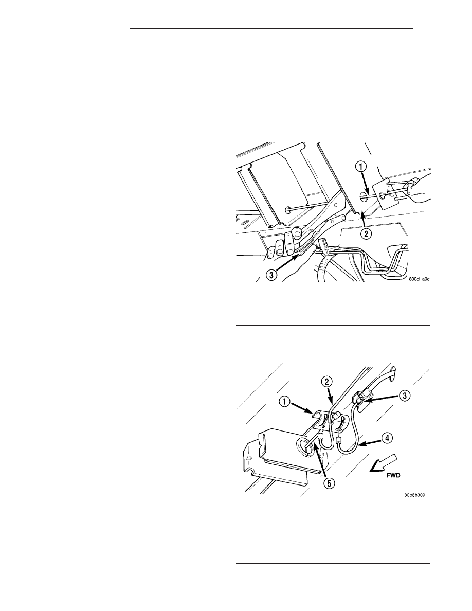
(1) Grasp the exposed section of the front parking
brake cable and pull rearward on it. While holding
the park brake in this position, install a pair of lock-
ing pliers on the front parking brake cable just rear-
ward of the second body outrigger bracket (Fig. 87).
(2) Remove the left rear and intermediate parking
brake cables from the parking brake cable equalizer
(Fig. 88).
Fig. 87 Locking Out Automatic Adjuster
1 - PARK BRAKE CABLE
2 - REAR BODY OUTRIGGER BRACKET
3 - LOCKING PLIERS
Fig. 88 Parking Brake Cable Attachment To
Equalizer
1 - EQUALIZER
2 - LEFT REAR PARKING BRAKE CABLE
3 - LOCKING NUT
4 - INTERMEDIATE PARKING BRAKE CABLE
5 - FRONT PARKING BRAKE CABLE
5 - 58
BRAKES - BASE
RS
PARKING BRAKE (Continued)