Chrysler Town, Dodge Caravan. Manual - part 50


  Index      Chrysler     Chrysler TOWN & COUNTRY, VOYAGER, Dodge Caravan - service repair manual 2001-2007 year


Search            


Content   ..  48  49  50  51   ..


Chrysler Town, Dodge Caravan. Manual - part 50


(7) Remove the screw fastening the proportioning

valve actuator rod bracket to the rear axle. Raise the
actuator lever to the full-upward position and hold it
there.

(8) With the aid of a helper, apply pressure to the

brake pedal until a pressure of 6895 kPa (1000 psi) is
obtained on the proportioning valve inlet gauge.
Then, based on the type of brake system the vehicle
is equipped with and the pressure specification
shown on the following table, compare the pressure
reading on the outlet gauge to the specification. If
outlet pressure at the proportioning valve is not
within specification when required inlet pressure is
obtained, replace the proportioning valve. (Refer to 5
-

BRAKES/HYDRAULIC/MECHANICAL/PROPOR-

TIONING VALVE - REMOVAL)

CAUTION: Do not attempt to adjust the height sens-
ing proportioning valve. If found to be defective,
replace the valve.

(9) Remove the pressure test fittings and pressure

gauges from the proportioning valve.

(10) Install the chassis brake lines in the correct

ports of the proportioning valve. Tighten all tube
nuts to 17 N·m (145 in. lbs.).

(11) If necessary, repeat the above steps on the

remaining side of the proportioning valve which con-
trol the other rear wheel brake.

(12) Attach the actuator lever and bracket to the

rear axle.

(13) Bleed rear brakes. (Refer to 5 - BRAKES -

STANDARD PROCEDURE)

(14) Road test vehicle.

PROPORTIONING VALVE SPECIFICATIONS

WHEEL

BASE

DRIVE

TRAIN

SALES CODE

BRAKE SYSTEM

SPLIT

POINT

SLOPE

INLET

PRESSURE

PSI

OUTLET

PRESSURE

PSI

SWB

FWD

BRB-BGF

15

9

DISC/DRUM

W/O ANTILOCK

VAR.

.59

1000 PSI

675-875 PSI

REMOVAL - PROPORTIONING VALVE (HEIGHT
SENSING)

(1) Using a brake pedal depressor, move and lock

the brake pedal to a position past its first 1 inch of
travel. This will prevent brake fluid from draining
out of the master cylinder when the brake tubes are
removed from the proportioning valve.

(2) Raise vehicle. (Refer to LUBRICATION &

MAINTENANCE/HOISTING - STANDARD PROCE-
DURE).

CAUTION: Before removing the brake tubes from
the proportioning valve, the proportioning valve and
the brake tubes must be thoroughly cleaned. This is
required to prevent contamination from entering the
proportioning valve or the brake tubes.

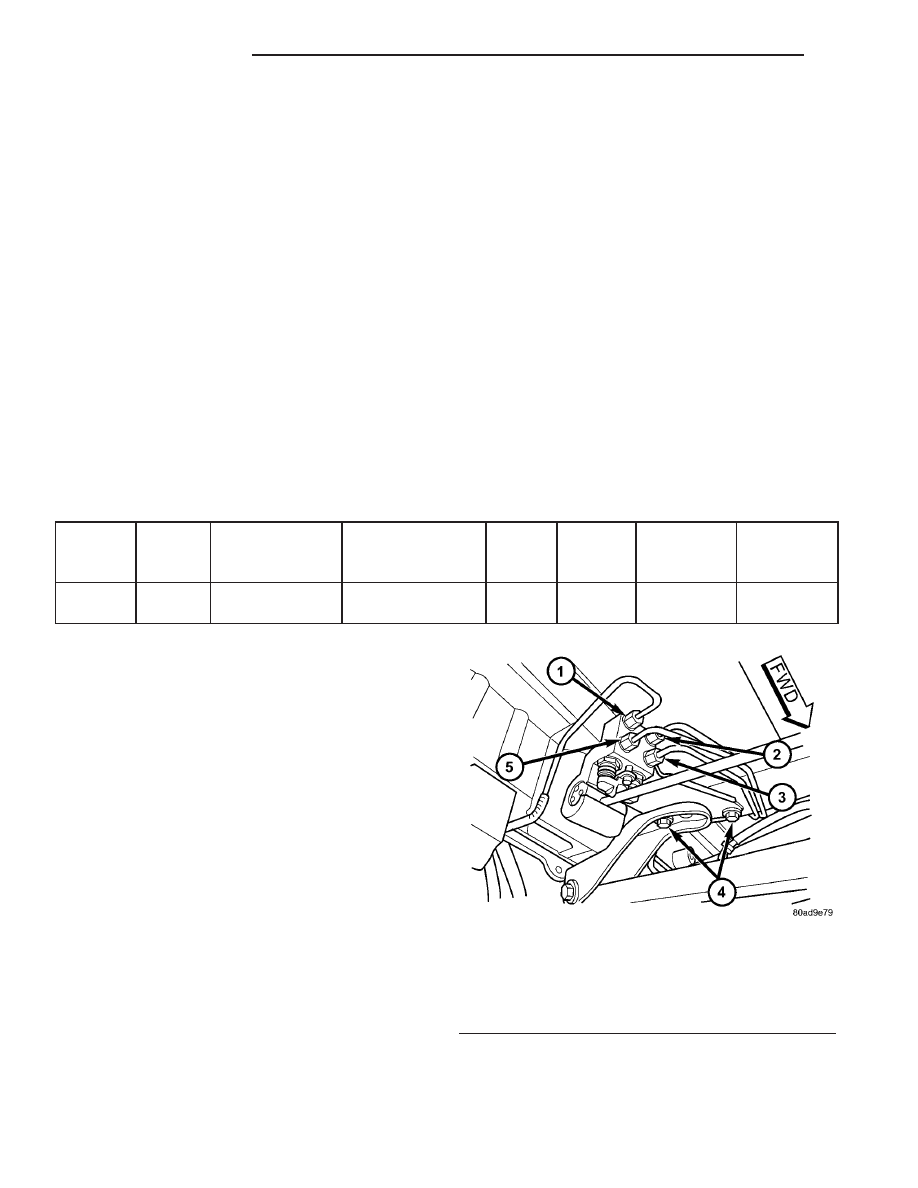
(3) Remove the four brake tubes from the inlet and

outlet ports of the proportioning valve (Fig. 73).

(4) Remove the two bolts attaching the proportion-

ing valve and bracket to the vehicle (Fig. 73).

(5) Slide the bracket out from under rear track bar

bracket. Lower the valve down enough to pull its
actuator rod out of the axle bracket and remove the
proportioning valve from the vehicle.

Fig. 73 PROPORTIONING VALVE MOUNTING

1 - LEFT REAR OUTLET TUBE
2 - RIGHT REAR OUTLET TUBE
3 - RIGHT REAR INLET TUBE
4 - MOUNTING BOLTS
5 - LEFT REAR INLET TUBE

5 - 50

BRAKES - BASE

RS

PROPORTIONING VALVE (Continued)

INSTALLATION - PROPORTIONING VALVE
(HEIGHT SENSING)

(1) Install the end of the actuator rod through the

axle bracket grommet and slide the proportioning
valve bracket under the rear track bar body bracket
(Fig. 73).

(2) Install the proportioning valve attaching bolts

(Fig. 73). Tighten the attaching bolts to a torque of
54 N·m (40 ft. lbs.).

(3) Install the four chassis brake lines into the

inlet and outlet ports of the proportioning valve (Fig.
73). Tighten all tube nuts to a torque of 17 N·m (145
in. lbs.).

CAUTION: The height sensing proportioning valve
is not adjustable. No attempt should be made to
adjust it.

(4) Bleed the brake system thoroughly to ensure

that all air has been expelled from the hydraulic sys-
tem. (Refer to 5 - BRAKES - BASE - STANDARD
PROCEDURE).

(5) Lower the vehicle to the ground.
(6) Road test the vehicle to verify proper operation

of the brake system.

ROTOR

DIAGNOSIS AND TESTING - BRAKE ROTOR

Any servicing of the rotor requires extreme care to

maintain the rotor within service tolerances to
ensure proper brake action.

Excessive runout or wobble in a rotor can increase

pedal travel due to piston knock-back. This increases
guide pin sleeve wear due to the tendency of the cal-
iper to follow the rotor wobble.

When diagnosing a brake noise or pulsation, the

machined disc braking surface should be checked and
inspected.

BRAKING SURFACE INSPECTION

Light braking surface scoring and wear is accept-

able. If heavy scoring or warping is evident, the rotor
must be refaced or replaced. (Refer to 5 - BRAKES/
HYDRAULIC/MECHANICAL/ROTORS

-

STAN-

DARD PROCEDURE).

Excessive wear and scoring of the rotor can cause

improper lining contact on the rotor’s braking sur-
face. If the ridges on the rotor are not removed before
new brake shoes are installed, improper wear of the
shoes will result.

If a vehicle has not been driven for a period of

time, the rotor’s braking surface will rust in the
areas not covered by the brake shoes at that time.
Once the vehicle is driven, noise and chatter from

the disc brakes can result when the brakes are
applied.

Some discoloration or wear of the rotor surface is

normal and does not require resurfacing when lin-
ings are replaced. If cracks or burned spots are evi-
dent, the rotor must be replaced.

ROTOR MINIMUM THICKNESS

Measure rotor thickness at the center of the brake

shoe contact surface. Replace the rotor if it is worn
below minimum thickness or if machining the rotor
will cause its thickness to fall below specifications.

CAUTION: Do not machine the rotor if it will cause
the rotor to fall below minimum thickness.

Minimum thickness specifications are cast on the

rotor’s unmachined surface (Fig. 74). Limits can also
be found in this section’s specification table. (Refer to
5 - BRAKES/HYDRAULIC/MECHANICAL/ROTOR -
SPECIFICATIONS)

ROTOR THICKNESS VARIATION

Thickness variation in a rotor’s braking surface

can result in pedal pulsation, chatter and surge. This
can also be caused by excessive runout in the rotor or
the hub.

Rotor thickness variation measurements should be

made in conjunction with measuring runout. Mea-
sure thickness of the brake rotor at 12 equal points
around the rotor braking surface with a micrometer
at a radius approximately 25 mm (1 inch) from edge
of rotor (Fig. 75). If thickness measurements vary
beyond the specification listed in the specifaction
table (Refer to 5 - BRAKES/HYDRAULIC/MECHAN-
ICAL/ROTOR - SPECIFICATIONS), the rotor should
be refaced or replaced. (Refer to 5 - BRAKES/HY-
DRAULIC/MECHANICAL/ROTORS

-

STANDARD

PROCEDURE).

Fig. 74 Minimum Brake Rotor Thickness Markings

(Typical)

1 - ROTOR MINIMUM THICKNESS MARKING
2 - ROTOR

RS

BRAKES - BASE

5 - 51

PROPORTIONING VALVE (Continued)

ROTOR RUNOUT

On-vehicle rotor runout is the combination of the

individual runout of the hub face and the runout of
the rotor. (The hub and rotor runouts are separable).
To measure rotor runout on the vehicle, first remove
the tire and wheel assembly. Reinstall the wheel
mounting nuts on the studs, tightening the rotor to
the hub. Mount the Dial Indicator, Special Tool
C-3339, with Mounting Adaptor, Special Tool SP-
1910 on steering arm. The dial indicator plunger
should contact braking surface of rotor approximately
ten millimeters from edge of rotor (Fig. 76). Check
lateral runout on both sides of the rotor, marking the
low and high spots on both. Runout limits can be
found in the specification table in this section. (Refer
to 5 - BRAKES/HYDRAULIC/MECHANICAL/RO-
TOR - SPECIFICATIONS)

If runout is in excess of the specification, check the

lateral runout of the hub face. Before removing the
rotor from the hub, place a chalk mark across both
the rotor and the one wheel stud closest to where the
high runout measurement was taken. This way, the
original mounting spot of the rotor on the hub is
indexed (Fig. 77).

Remove the rotor from the hub.

NOTE: Clean the hub face surface before checking
runout. This provides a clean surface to get an
accurate indicator reading.

Mount Dial Indicator, Special Tool C-3339, and

Mounting Adaptor, Special Tool SP-1910, to the steer-
ing knuckle. Position the indicator stem so it contacts
the hub face near the outer diameter. Care must be
taken to position stem outside of the stud circle, but
inside of the chamfer on the hub rim (Fig. 78).

Hub runout should not exceed 0.03 mm (0.0012

inch). If runout exceeds this specification, the hub
must be replaced. (Refer to 2 - SUSPENSION/
FRONT/HUB / BEARING - REMOVAL)(Refer to 2 -
SUSPENSION/REAR/HUB / BEARING - REMOVAL)

If the hub runout does not exceed this specifica-

tion, install the rotor back on the hub, aligning the
chalk marks on the rotor with a wheel mounting

Fig. 75 Checking Rotor For Thickness

1 - CALIPER

Fig. 76 Checking Rotor Runout

1 - SPECIAL TOOL SP-1910
2 - 10 MILLIMETERS FROM EDGE
3 - DISC SURFACE
4 - SPECIAL TOOL C-3339

Fig. 77 Marking Rotor and Wheel Stud

1 - CHALK MARK

5 - 52

BRAKES - BASE

RS

ROTOR (Continued)

stud, two studs apart from the original stud (Fig. 79).
Tighten nuts in the proper sequence and torque to
specifications.

Recheck brake rotor runout to see if the runout is

now within specifications. (Refer to 5 - BRAKES/HY-
DRAULIC/MECHANICAL/ROTOR

-

SPECIFICA-

TIONS)

If runout is not within specifications, reface or

replace the brake rotor. (Refer to 5 - BRAKES/HY-
DRAULIC/MECHANICAL/ROTORS

-

STANDARD

PROCEDURE)

STANDARD PROCEDURE - BRAKE ROTOR
MACHINING

NOTE: Refacing the rotor is not required each time
the brake pads are replaced, only when the need is
foreseen.

Any servicing of the rotor requires extreme care to

maintain the rotor within service tolerances to
ensure proper brake action.

If the rotor surface is deeply scored or warped, or

there is a complaint of brake roughness or brake
pedal pulsation, the rotor should be refaced using a
hub-mounted

on-car

brake

lathe

(Fig.

80),

or

replaced.

The use of a hub-mounted on-car brake lathe is

highly recommended to eliminate the possibility of
excessive runout. It trues the brake rotor to the vehi-
cle’s hub and bearing.

NOTE: All rotors have markings for minimum allow-
able thickness cast on an un-machined surface of
the rotor (Fig. 81) (Fig. 82). Minimum thickness
specifications can also be found in the specification
table in this section. (Refer to 5 - BRAKES/HY-
DRAULIC/MECHANICAL/ROTOR - SPECIFICATIONS)

Minimum allowable thickness is the minimum

thickness which the brake rotor machined surface
may be cut to.

CAUTION: Do not machine the rotor if it will cause
the rotor to fall below minimum thickness.

Fig. 78 Checking Hub Runout

1 - HUB SURFACE
2 - SPECIAL TOOL C-3339
3 - SPECIAL TOOL SP-1910

Fig. 79 Index Rotor And Wheel Stud

1 - CHALK MARK

Fig. 80 On-Car Brake Lathe

1 - ON-CAR BRAKE LATHE

RS

BRAKES - BASE

5 - 53

ROTOR (Continued)


Content   ..  48  49  50  51   ..