Chrysler Town, Dodge Caravan. Manual - part 49


  Index      Chrysler     Chrysler TOWN & COUNTRY, VOYAGER, Dodge Caravan - service repair manual 2001-2007 year


Search            


Content   ..  47  48  49  50   ..


Chrysler Town, Dodge Caravan. Manual - part 49


INSTALLATION

INSTALLATION - LHD

(1) Position power brake booster on dash panel

using the reverse procedure of its removal (Fig. 62).
It may be necessary to push in on booster input rod
as it is guided through the dash panel.

(2) Install the four nuts mounting the booster to

the dash panel (Fig. 61). Tighten the mounting nuts
to a torque of 29 N·m (250 in. lbs.).

(3) Using lubriplate, or equivalent, coat the sur-

face of the brake pedal pin where it contacts the
booster input rod.

CAUTION: When installing the brake pedal pin on
the power brake booster input rod, do not re-use
the old retaining clip.

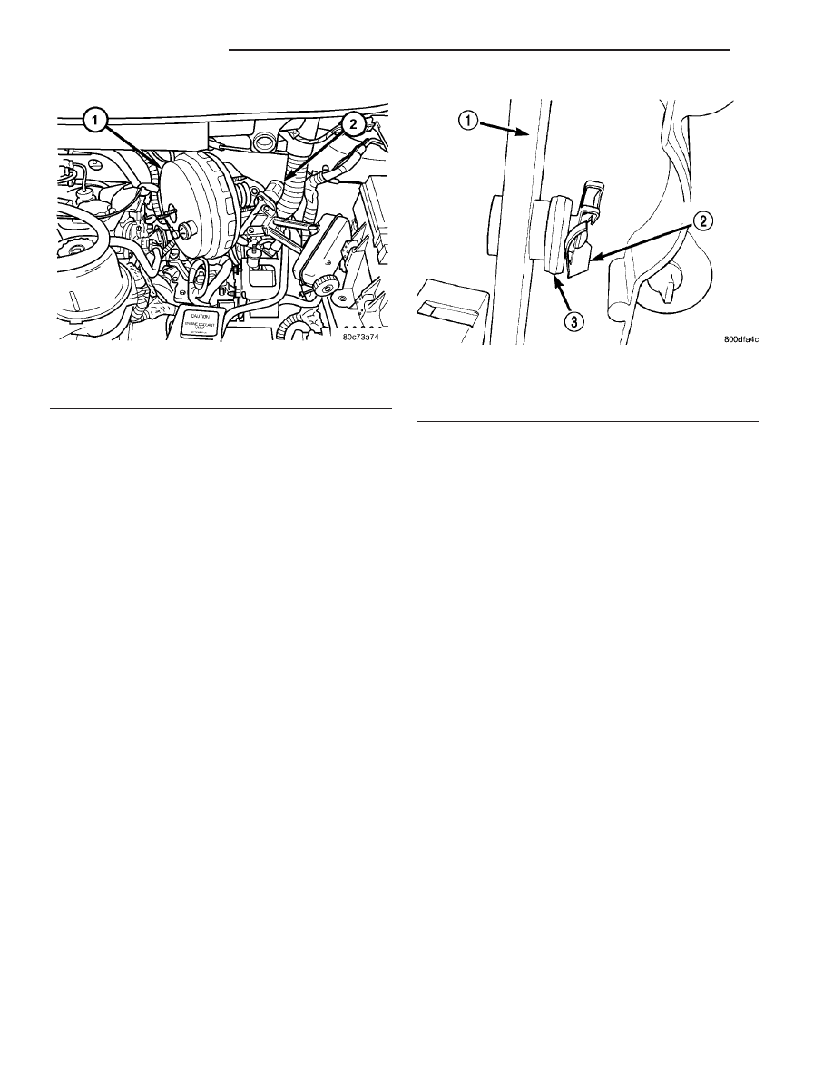
(4) Install booster input rod on brake pedal pin

and install a NEW retaining clip (Fig. 68).

CAUTION: Do not reuse the original brake lamp
switch. The switch can only be adjusted once. That
is during initial installation of the switch. If the
switch

is

not

adjusted

properly

or

has

been

removed for some service, a new switch must be
installed and adjusted.

(5) Remove and replace the brake lamp switch

with a NEW switch. (Refer to 8 - ELECTRICAL/
LAMPS/LIGHTING

-

EXTERIOR/BRAKE

LAMP

SWITCH - REMOVAL), (Refer to 8 - ELECTRICAL/
LAMPS/LIGHTING

-

EXTERIOR/BRAKE

LAMP

SWITCH - INSTALLATION)

(6) Install the silencer panel below the steering

column.

(7) Connect vacuum hose to check valve on power

brake booster.

CAUTION: The master cylinder (and its rear seal) is
used to create the seal for holding vacuum in the
vacuum booster. The vacuum seal on the master
cylinder MUST be replaced with a NEW seal when-
ever the master cylinder is removed from the vac-
uum booster.

CAUTION: When removing the vacuum seal from
the master cylinder do not use a sharp tool.

(8) Using a soft tool such as a trim stick, remove

the vacuum seal from the master cylinder mounting
flange.

(9) Install a NEW vacuum seal on rear mounting

flange of the master cylinder (Fig. 69).

(10) Position master cylinder on studs of booster,

aligning push rod on booster with master cylinder
piston.

(11) Install the two nuts mounting the master cyl-

inder to the booster (Fig. 59). Tighten both mounting
nuts to a torque of 25 N·m (225 in. lbs.).

(12) Connect wiring harness connector to brake

fluid level switch in the master cylinder fluid reser-
voir (Fig. 58).

(13) Connect primary and secondary brake tubes

to ABS ICU or non-ABS junction block (Fig. 59).
Tighten the tube nuts to 17 N·m (145 in lbs.).

(14) Install wiper module (unit). (Refer to 8 -

ELECTRICAL/WIPERS/WASHERS/WIPER

MOD-

ULE - INSTALLATION)

(15) If equipped with speed control, install speed

control servo and connect wiring connector. Tighten

Fig. 67 RHD Booster Removal/Installation

1 - POWER BRAKE BOOSTER
2 - MASTER CYLINDER

Fig. 68 Retaining Pin Installed On Brake Pedal Pin

1 - BRAKE PEDAL
2 - RETAINING CLIP
3 - BOOSTER INPUT ROD

5 - 46

BRAKES - BASE

RS

POWER BRAKE BOOSTER (Continued)

the mounting nuts to a torque of 14 N·m (124 in.
lbs.).

(16) Install the battery tray. Install the two nuts

and one bolt attaching the battery tray to the vehicle.
Tighten the bolt and nuts to a torque of 14 N·m (124
in. lbs.).

(17) If vehicle is equipped with speed control, con-

nect the servo vacuum hose to the vacuum tank on
the battery tray.

(18) Install the air inlet resonator and hoses as an

assembly on the throttle body and air cleaner hous-
ing. Securely tighten hose clamp at air cleaner hous-
ing and throttle body.

(19) Secure the engine coolant filler neck to the

battery tray with its mounting screw.

(20) Install the battery, clamp and mounting nut.
(21) Install the positive battery cable on the bat-

tery.

(22) Install the negative battery cable on the bat-

tery.

(23) Install the battery thermal guard shield.
(24) Bleed the base brakes as necessary. (Refer to

5 - BRAKES - STANDARD PROCEDURE)

(25) Road test vehicle to ensure operation of the

brakes.

INSTALLATION - RHD

(1) Position power brake booster on dash panel

using the reverse procedure of its removal (Fig. 67).

(2) Below instrument panel, first install the two

upper nuts mounting the booster to the dash panel,
drawing it into place, then install the two lower
mounting nuts. Tighten the mounting nuts to a
torque of 29 N·m (250 in. lbs.).

(3) Using lubriplate, or equivalent, coat the sur-

face of the brake pedal torque shaft pin where it con-
tacts the booster input rod.

CAUTION: When installing the brake pedal torque
shaft pin on the power brake booster input rod, do
not re-use the old retaining clip.

(4) Install booster input rod on brake pedal torque

shaft pin and install a NEW retaining clip (Fig. 70).

(5) Install booster input rod trim cover.
(6) Connect vacuum hose to check valve on power

brake booster.

CAUTION: The master cylinder (and its rear seal) is
used to create the seal for holding vacuum in the
vacuum booster. The vacuum seal on the master
cylinder MUST be replaced with a NEW seal when-
ever the master cylinder is removed from the vac-
uum booster.

CAUTION: When removing the vacuum seal from
the master cylinder, do not use a sharp tool.

(7) Using a soft tool such as a trim stick, remove

the vacuum seal from the master cylinder mounting
flange.

(8) Install a NEW vacuum seal on rear mounting

flange of the master cylinder (Fig. 71).

(9) Position master cylinder on studs of booster,

aligning push rod on booster with master cylinder
piston.

(10) Install the two nuts mounting the master cyl-

inder to the booster (Fig. 64). Tighten both mounting
nuts to a torque of 25 N·m (225 in. lbs.).

(11) Connect wiring harness connector to brake

fluid level switch in the master cylinder fluid reser-
voir (Fig. 63).

Fig. 69 Vacuum Seal (Typical)

1 - MASTER CYLINDER ASSEMBLY
2 - VACUUM SEAL

Fig. 70 Retaining Pin Installed On Brake Pedal Pin

(Typical)

1 - BRAKE PEDAL
2 - RETAINING CLIP
3 - BOOSTER INPUT ROD

RS

BRAKES - BASE

5 - 47

POWER BRAKE BOOSTER (Continued)

(12) If the vehicle is equipped with the 2.5L diesel

engine, install the coolant recovery pressure con-
tainer and bracket. (Refer to 7 - COOLING/ENGINE/
COOLANT

RECOVERY

PRESS

CONTAINER

-

INSTALLATION)

(13) If equipped with speed control, install speed

control servo and connect wiring connector. Tighten
the mounting nuts to a torque of 14 N·m (124 in.
lbs.).

(14) Install the battery tray. Install the two nuts

and one bolt attaching the battery tray to the vehicle.
Tighten the bolt and nuts to a torque of 14 N·m (124
in. lbs.).

(15) If vehicle is equipped with speed control, con-

nect the servo vacuum hose to the vacuum tank on
the battery tray.

(16) Install the battery, clamp and mounting nut.
(17) Install the positive battery cable on the bat-

tery.

(18) Install the negative battery cable on the bat-

tery.

(19) Install the battery thermal guard shield.

CAUTION: Do not reuse the original brake lamp
switch. The switch can only be adjusted once. That
is during initial installation of the switch. If the
switch

is

not

adjusted

properly

or

has

been

removed for some service, a new switch must be
installed and adjusted.

(20) Remove and replace the brake lamp switch

with a NEW switch. (Refer to 8 - ELECTRICAL/
LAMPS/LIGHTING

-

EXTERIOR/BRAKE

LAMP

SWITCH - REMOVAL), (Refer to 8 - ELECTRICAL/
LAMPS/LIGHTING

-

EXTERIOR/BRAKE

LAMP

SWITCH - INSTALLATION)

(21) Bleed the base brakes as necessary. (Refer to

5 - BRAKES - STANDARD PROCEDURE)

(22) Road test vehicle to ensure proper operation

of the brakes.

PROPORTIONING VALVE

DESCRIPTION - PROPORTIONING VALVE
(HEIGHT SENSING)

NOTE: Only vehicles without antilock brakes (ABS)
have a proportioning valve. Vehicles with ABS uti-
lize electronic brake distribution which is controlled
through the ABS integrated control unit.

Vehicles not equipped with ABS use a height sens-

ing proportioning valve. It is mounted to the body of
the vehicle above the rear axle (Fig. 72). It has an
actuator lever that attaches to the rear axle and
moves with the axle to help the valve sense the vehi-
cle height.

CAUTION: The height sensing proportioning valve
is not adjustable. No attempt should be made to
adjust it. It is replaced as a complete assembly.

CAUTION: The use of after-market load leveling or
load capacity increasing devices on this vehicle are
prohibited. Using air shock absorbers or helper
springs on this vehicle will cause the height sens-
ing proportioning valve to inappropriately reduce
the hydraulic pressure to the rear brakes. This inap-
propriate reduction in hydraulic pressure potentially
could result in increased stopping distance of the
vehicle.

OPERATION - PROPORTIONING VALVE
(HEIGHT SENSING)

Vehicles not equipped with ABS use a height sens-

ing proportioning valve.

The height sensing proportioning valve operates

similarly to a standard proportioning valve in the fol-
lowing way. As hydraulic pressure is applied to the
valve, full input hydraulic pressure is supplied to the
rear brakes up to a certain pressure point, called the
split point. Beyond the split point, the proportioning
valve reduces the amount of hydraulic pressure to
the rear brakes according to a given ratio. Thus, on
light

brake

applications,

approximately

equal

hydraulic pressure will be transmitted to both the
front and rear brakes. Upon heavier brake applica-
tions, the hydraulic pressure transmitted to the rear
brakes will be lower than the front brakes. This will
prevent premature rear wheel lockup and skid.

Fig. 71 Vacuum Seal (Typical)

1 - MASTER CYLINDER ASSEMBLY
2 - VACUUM SEAL

5 - 48

BRAKES - BASE

RS

POWER BRAKE BOOSTER (Continued)

Here is how the height sensing proportioning valve

differs from a standard proportioning valve. As the
height of the rear suspension changes, the height
sensing portion of the proportioning valve changes
the split point of the proportioning valve. When the
height of the rear suspension is low, the proportion-
ing valve interprets this as extra load and the split
point of the proportioning valve is raised to a higher
pressure to allow for more rear braking. When the
height of the rear suspension is high, the proportion-
ing valve interprets this as a light load and the split
point of the proportioning valve is lowered to a lower
pressure and rear braking is reduced.

The height sensing proportioning valve regulates

the pressure by sensing the load condition of the
vehicle through the movement of the proportioning
valve actuator lever (Fig. 72). As the position of the
rear axle changes, depending on the load the vehicle
is carrying, the movement is transferred to the pro-
portioning valve. The proportioning valve adjusts the
hydraulic pressure accordingly.

The height sensing proportioning valve allows the

brake system to maintain the optimal front to rear
brake balance regardless of the vehicle load condi-
tion. Under a light load condition, hydraulic pressure
to the rear brakes is minimized. As the rear load con-
dition increases, so does the hydraulic pressure to
the rear brakes.

DIAGNOSIS AND TESTING - PROPORTIONING
VALVE (HEIGHT SENSING)

CAUTION: The use of aftermarket load leveling or
load capacity increasing devices on this vehicle is
prohibited. Using air shock absorbers or helper

springs on this vehicle will cause the height sens-
ing proportioning valve to inappropriately reduce
the hydraulic pressure to the rear brakes. This inap-
propriate reduction in hydraulic pressure potentially
could result in increased stopping distance of the
vehicle.

When a premature rear wheel skid is obtained on a

brake application, it may be an indication that the
hydraulic pressure to the rear brakes is above the
specified output from the proportioning valve. This
condition indicates a possible malfunction of the
height

sensing

proportioning

valve,

which

will

require testing to verify that it is properly controlling
the hydraulic pressure allowed to the rear brakes.
Premature rear wheel skid may also be caused by
contaminated front or rear brake linings.

Prior to testing a proportioning valve for function,

check that all tire pressures are correct. Also, ensure
the front and rear brake linings are in satisfactory
condition. It is also necessary to verify that the
brakes shoe assemblies on a vehicle being
tested are either original equipment manufac-
turers (OEM) or original replacement brake
shoe assemblies meeting the OEM lining mate-
rial specification. This vehicles brake system is
not balanced for aftermarket brake shoe assem-
bly lining material.

If both front and rear brakes check OK, proceed

with the following test procedure for the height sens-
ing proportioning valve.

(1) Road test the vehicle to determine which rear

wheel brake is exhibiting premature wheel skid.

(2) Raise vehicle. (Refer to LUBRICATION &

MAINTENANCE/HOISTING - STANDARD PROCE-
DURE)

(3) Remove the chassis brake tube going to the

rear brake in question at the proportioning valve.
Remove the chassis brake tube coming from the junc-
tion block at the proportioning valve (Fig. 73).

(4) Install the appropriate fittings from Pressure

Test Fittings, Special Tool 6833, into the open ports
of the proportioning valve.

(5) Install the previously removed brake lines into

the Pressure Test Fittings. Tighten all tube nuts to
17 N·m (145 in. lbs.).

(6) Install a pressure gauge from Gauge Set, Spe-

cial Tool C-4007-A into the open port on each pres-
sure test fitting. Bleed air out of hose from pressure
test fittings to pressure gauges at the pressure
gauges. Then bleed air out of the brake line being
tested at that rear wheel brake bleeder.

NOTE: Actuator rod is a linear spring and is meant
to flex by design. When rod is raised, it will have
some curvature to it.

Fig. 72 HEIGHT SENSING PROPORTIONING VALVE

1 - PROPORTIONING VALVE
2 - ACTUATOR LEVER
3 - AXLE BRACKET
4 - REAR AXLE

RS

BRAKES - BASE

5 - 49

PROPORTIONING VALVE (Continued)


Content   ..  47  48  49  50   ..