Chrysler Town, Dodge Caravan. Manual - part 22


  Index      Chrysler     Chrysler TOWN & COUNTRY, VOYAGER, Dodge Caravan - service repair manual 2001-2007 year


Search            


Content   ..  20  21  22  23   ..


Chrysler Town, Dodge Caravan. Manual - part 22


SPRING MOUNTS - FRONT

REMOVAL

(1) Raise vehicle on frame-contact hoist as follows:

(a) Position the hoist arm supporting the corner

of the vehicle to be serviced against a block of wood
placed on the body sill as shown (Fig. 37).

(b) Position the remaining hoist arms at each

corner of the vehicle in the normal fashion. (Refer
to LUBRICATION & MAINTENANCE/HOISTING
- STANDARD PROCEDURE)

(c) Raise the vehicle to a comfortable working

level.

(2) Position an under-hoist utility jack or transmis-

sion jack under rear axle toward the side needing
bushing replacement. Jack pad should just contact
axle.

(3) Remove shock absorber lower mounting bolt.

NOTE: If shock absorber bolt deflects upward dur-
ing removal, raise axle by adjusting support jack. If
shock absorber bolt deflects downward during
removal, lower axle by adjusting support jack (or by
pulling on axle).

(4) Remove four bolts securing leaf spring front

mounting bracket to the body (Fig. 37).

(5) Using jack, slowly lower rear axle, permitting

the forward end of rear spring to hang down. Lower
it enough to allow access to spring pivot bolt. It may
be necessary to place a wooden block between the
spring and vehicle to hold forward end of the spring
in place.

(6) Remove leaf spring forward pivot bolt, then

remove mounting bracket.

INSTALLATION

(1) Position spring mounting bracket over spring

eye and install pivot bolt through center of bushing
from the outboard side.

NOTE: The pivot bolt must be installed from the
outboard side to allow proper bracket to body
mounting.

(2) Install the nut on the pivot bolt and lightly

tighten. Do not fully tighten bolt at this time.

(3) Raise the under-hoist utility jack or transmis-

sion jack, guiding the forward mounting bracket into
place against the body. It may help to use a drift
punch placed through the hole centered between the
mounting bolt holes in the bracket and the pilot hole
in the body of the vehicle as a guide. When the four
mounting bolt holes line up with their threads in the
body, Install the mounting bolts (Fig. 37). Tighten the
four mounting bolts to 61 N·m (45 ft. lbs.) torque.

(4) Raise or lower the jack until shock absorber

lower eye aligns with threads in axle housing. Install
shock absorber lower mounting bolt. Do not fully
tighten bolt at this time.

(5) Lower the vehicle and remove hoist arms and

block of wood from under vehicle.

(6) Tighten the spring front pivot bolt to 156 N·m

(115 ft. lbs.) torque.

(7) Tighten the lower shock absorber mounting

bolt to 88 N·m (65 ft. lbs.) torque.

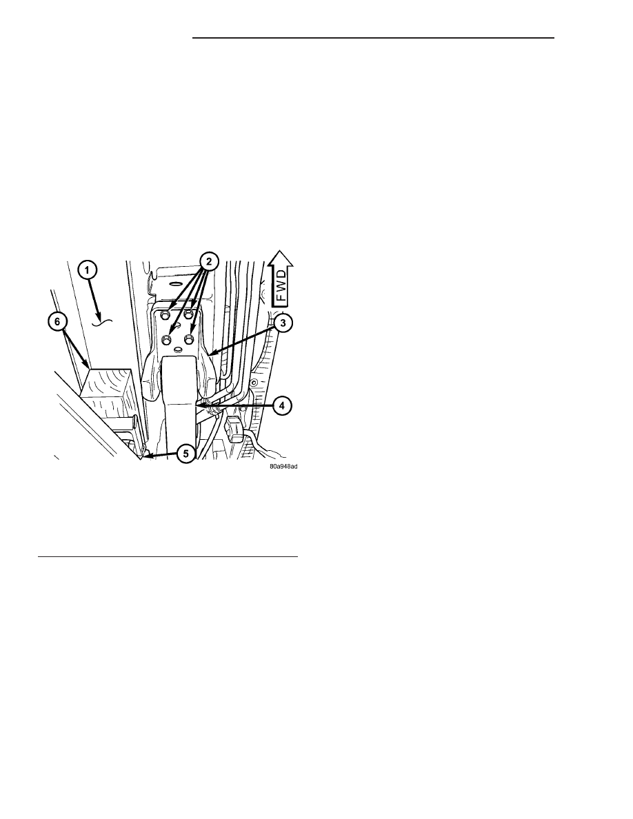
Fig. 37 LIFTING POINT AND SPRING MOUNT

1 - BODY SILL AREA
2 - MOUNTING BOLTS
3 - SPRING MOUNTING BRACKET
4 - LEAF SPRING
5 - HOIST LIFT ARM
6 - WOODEN BLOCK

2 - 42

REAR SUSPENSION

RS

SPRING MOUNTS - REAR

REMOVAL

(1) Remove the attaching nuts and bolts from the

leaf spring rear shackle (Fig. 38) and (Fig. 39).

(2) Install a jackstand under the side of the axle

having the leaf spring mount removed. Using the
jackstand, support the weight of the axle and leaf
spring.

(3) Remove the lower mounting bolt from the

shock absorber.

(4) Remove the bolts attaching the leaf spring rear

mount to the body of the vehicle (Fig. 40).

(5) Lower the jackstand and the rear of the leaf

spring. Remove the shackle from the leaf spring
bushing.

INSTALLATION

CAUTION: The following sequence must be fol-
lowed when tightening the pin nuts on the rear
hanger for the rear leaf spring. First the hanger pin
nuts must be tightened to the specified torque.
Then tighten the retaining bolts for the inner to
outer half of the spring hanger to the specified
torque. This sequence must be followed to avoid
bending the spring hanger.

(1) For installation, reverse removal procedure. Do

not tighten rear spring shackle nuts fully until vehi-
cle is lowered and the full vehicle weight is applied
to the rear wheels. Tighten rear spring mount bolts
to 61 N·m (45 ft. lbs.). Tighten shackle nuts to 61
N·m (45 ft. lbs.).

STABILIZER BAR

DESCRIPTION

Front-wheel-drive models use a stabilizer bar that

is mounted behind the rear axle. All-wheel-drive
models use a stabilizer bar that is mounted in front
of the rear axle.

The stabilizer bar interconnects both sides of the

rear axle and attaches to the rear frame rails using 2
rubber isolated link arms.

Both type stabilizer bars have the same basic com-

ponents. Attachment to the rear axle tube, and rear
frame rails is through rubber-isolated bushings.

Fig. 38 Leaf Spring Shackle Nuts (FWD)

1 - SHACKLE PLATE

Fig. 39 All-Wheel-Drive Rear Suspension

1 - SHACKLE
2 - REAR MOUNT (HANGER)
3 - LEAF SPRING (MULTI-LEAF)
4 - AWD REAR AXLE

Fig. 40 Rear Spring Mount

1 - LEAF SPRING MOUNT

RS

REAR SUSPENSION

2 - 43

The 2 rubber isolated links are connected to the

rear frame rails by brackets. These brackets are
bolted to the bottom of the frame rails.

OPERATION

Jounce and rebound movements affecting one

wheel are partially transmitted to the opposite wheel
to reduce body roll.

REMOVAL

REMOVAL - AWD

(1) Raise vehicle. (Refer to LUBRICATION &

MAINTENANCE/HOISTING - STANDARD PROCE-
DURE)

(2) Remove the bolts securing the stabilizer bar to

links on each end of the bar.

(3) While holding the stabilizer bar in place,

remove the bolts that attach the stabilizer bar bush-
ing retainers to the rear axle.

(4) Remove the stabilizer bar from the vehicle.
(5) If the links need to be serviced, remove the

upper link arm to bracket bolt. Then remove link
arm from frame rail attaching bracket.

REMOVAL - FWD

(1) Raise vehicle. See Hoisting in Lubrication and

Maintenance.

(2) Remove the bolts securing the stabilizer bar to

links on each side of bar.

(3) While holding the stabilizer bar in place,

remove the bolts that attach the stabilizer bar bush-
ing retainers to the rear axle.

(4) Remove the stabilizer bar from the vehicle.

INSTALLATION

INSTALLATION - AWD

(1) Install the stabilizer bar on the rear axle.
(2) Install bushing retainer bolts. Do not tighten at

this time.

(3) Install bolts connecting links to stabilizer bar.

Do not tighten at this time.

(4) Lower the vehicle so that the full weight of the

vehicle is on all four tires. With the vehicle at its
curb height, tighten the following bolts to the torques
listed:

• Stabilizer bar bushing retainer-to-axle bracket

bolts — 61 N·m (45 ft. lbs.)

• Stabilizer bar-to-link bolts — 61 N·m (45 ft. lbs.)

INSTALLATION - FWD

(1) Lift the stabilizer bar onto the rear axle and

install the two retainer mounting bolts. DO NOT
TIGHTEN.

(2) Install the bolts attaching the stabilizer bar

links to the stabilizer bar. DO NOT TIGHTEN.

(3) Lower the vehicle so that the full weight of the

vehicle is on all four tires. With the vehicle at its
curb height, tighten the following bolts to the torques
listed:

• Stabilizer bar bushing retainer-to-axle bracket

bolts — 61 N·m (45 ft. lbs.)

• Stabilizer bar-to-link — 61 N·m (45 ft. lbs.)

TRACK BAR

DESCRIPTION

On front-wheel-drive applications of this vehicle

that are equipped with single leaf rear springs, a
track bar is used on the rear axle (Fig. 1).

The track bar connects the rear axle to the frame/

body of the vehicle. The track bar is isolated from the
body of the vehicle by an isolator bushing located in
each end of the track bar.

OPERATION

The track bar prevents excessive side-to-side move-

ment of the rear axle. The track bar is used to keep
the location of the axle in the correct position for
optimum handling and control of the vehicle.

REMOVAL

(1) Remove the nut and bolt mounting the track

bar to the rear axle (Fig. 41).

Fig. 41 Track Bar Mounting To Axle (Typical)

1 - LOWER TRACK BAR BOLT INSTALLATION

2 - 44

REAR SUSPENSION

RS

STABILIZER BAR (Continued)

(2) Remove the nut and bolt attaching the track

bar to the track bar mount on the body of the vehicle.
Remove the track bar from the track bar mount.

INSTALLATION

(1) Install the track bar first into the body mount

for the track bar (Fig. 42). Install the track bar bolt
with the head of the bolt facing toward the rear of
the vehicle (Fig. 43). Do not tighten.

(2) Install the track bar into its mounting bracket

on the rear axle (Fig. 41). Install the track bar bolt
with the head of the bolt facing toward the rear of
the vehicle. Do not tighten.

(3) Lower the vehicle to the ground until the full

weight of the vehicle is supported by the wheels.
Tighten both track bar attaching bolts to a torque of
95 N·m (70 ft. lbs.).

Fig. 42 Track Bar Installation (Typical)

1 - TRACK BAR REPLACEMENT

Fig. 43 Track Bar Bolt Installation

1 - TRACK BAR BOLT

RS

REAR SUSPENSION

2 - 45

TRACK BAR (Continued)


Content   ..  20  21  22  23   ..