Chrysler Town, Dodge Caravan. Manual - part 23


  Index      Chrysler     Chrysler TOWN & COUNTRY, VOYAGER, Dodge Caravan - service repair manual 2001-2007 year


Search            


Content   ..  21  22  23  24   ..


Chrysler Town, Dodge Caravan. Manual - part 23


WHEEL ALIGNMENT

TABLE OF CONTENTS

page

page

WHEEL ALIGNMENT

DESCRIPTION - WHEEL ALIGNMENT

. . . . . . . 46

DIAGNOSIS AND TESTING - SUSPENSION

AND STEERING

. . . . . . . . . . . . . . . . . . . . . . 49

STANDARD PROCEDURE

STANDARD PROCEDURE - WHEEL

ALIGNMENT . . . . . . . . . . . . . . . . . . . . . . . . . 51

STANDARD PROCEDURE - CURB HEIGHT

MEASUREMENT . . . . . . . . . . . . . . . . . . . . . . 54

SPECIFICATIONS

WHEEL ALIGNMENT

. . . . . . . . . . . . . . . . . . . 55

WHEEL ALIGNMENT

DESCRIPTION - WHEEL ALIGNMENT

Vehicle wheel alignment is the positioning of all

interrelated front and rear suspension angles. These
angles affect the handling and steering of the vehicle
when it is in motion. Proper wheel alignment is
essential for efficient steering, good directional stabil-
ity, and proper tire wear.

The method of checking a vehicle’s front and rear

wheel alignment varies depending on the manufac-
turer and type of equipment used. The manufactur-
er’s instructions should always be followed to ensure
accuracy

of

the

alignment,

except

when

DaimlerChrysler Corporation’s wheel alignment spec-
ifications differ.

On this vehicle, the suspension angles that can be

adjusted are as follows:

• Front Camber (with camber bolt package and

standard procedure)

• Front Toe
Check the wheel alignment and make all wheel

alignment adjustments with the vehicle standing at
its proper curb height specification. Curb height is
the normal riding height of the vehicle. It is mea-
sured from a certain point on the vehicle to the
ground or a designated area while the vehicle is sit-
ting on a flat, level surface. Refer to Curb Height
Measurement in this section for additional informa-
tion.

Typical wheel alignment angles and measurements

are described in the following paragraphs.
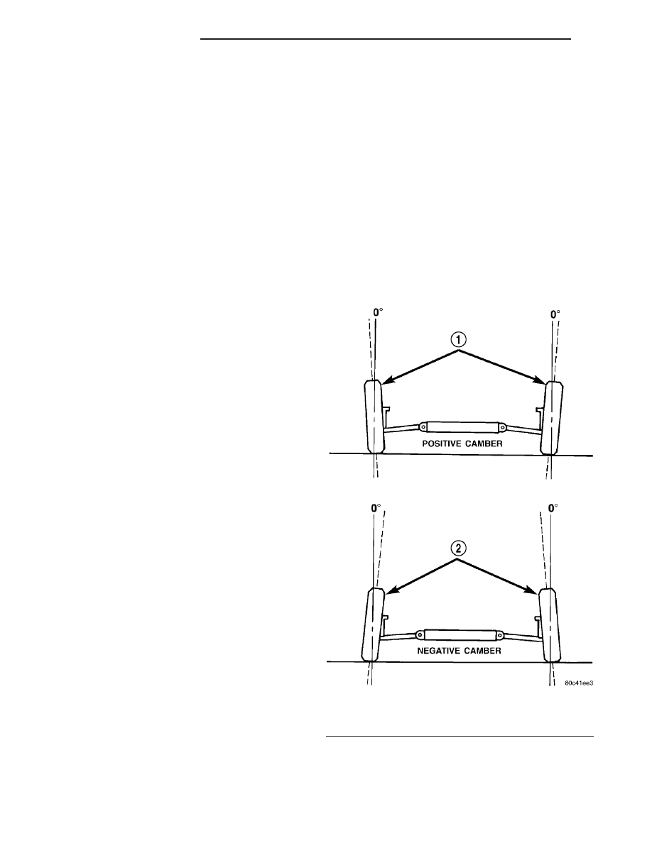
CAMBER

Camber is the inward or outward tilt of the top of

the tire and wheel assembly (Fig. 1). Camber is mea-
sured in degrees of angle relative to a true vertical
line. Camber is a tire wearing angle.

• Excessive negative camber will cause tread wear

at the inside of the tire.

• Excessive positive camber will cause tread wear

on the outside of the tire.

CROSS CAMBER

Cross camber is the difference between left and

right camber. To achieve the cross camber reading,
subtract the right side camber reading from the left.

Fig. 1 Camber

1 - WHEELS TILTED OUT AT TOP
2 - WHEELS TILTED IN AT TOP

2 - 46

WHEEL ALIGNMENT

RS

For example, if the left camber is +0.3° and the right
camber is 0.0°, the cross camber would be +0.3°.

CASTER

Caster is the forward or rearward tilt of the steer-

ing knuckle in reference to the position of the upper
and lower ball joints. Caster is measured in degrees
of angle relative to a true vertical center line. This
line is viewed from the side of the tire and wheel
assembly (Fig. 2).

• Forward tilt (upper ball joint ahead of lower)

results in a negative caster angle.

• Rearward tilt (upper ball joint trailing lower)

results in a positive caster angle.

Although caster does not affect tire wear, a caster

imbalance between the two front wheels may cause
the vehicle to lead to the side with the least positive
caster.

CROSS CASTER

Cross caster is the difference between left and

right caster.

TOE

Toe is the inward or outward angle of the wheels

as viewed from above the vehicle (Fig. 3).

• Toe-in is produced when the front edges of the

wheels on the same axle are closer together than the
rear edges.

• Toe-out is produced when the front edges of the

wheels on the same axle are farther apart than the
rear edges.

Toe-in and toe-out can occur at the front wheels

and the rear wheels.

Toe is measured in degrees or inches. The mea-

surement identifies the amount that the front of the
wheels point inward (toe-in) or outward (toe-out). Toe
is measured at the spindle height. Zero toe means
the front and rear edges of the wheels on the same
axle are equally distant.

Fig. 2 Caster

Fig. 3 Toe

1 - TOE-IN
2 - TOE-OUT

RS

WHEEL ALIGNMENT

2 - 47

WHEEL ALIGNMENT (Continued)

TOE-OUT ON TURNS

Toe-out on turns is the relative positioning of the

front wheels while steering through a turn (Fig. 4).
This compensates for each front wheel’s turning
radius. As the vehicle encounters a turn, the out-
board wheel must travel in a larger radius circle
than the inboard wheel. The steering system is
designed to make each wheel follow its particular
radius circle. To accomplish this, the front wheels
must progressively toe outward as the steering is
turned from center. This eliminates tire scrubbing
and undue tire wear when steering a vehicle through
a turn.

DYNAMIC TOE PATTERN

Dynamic toe pattern is the inward and outward toe

movement of the front and rear tires through the
suspension’s jounce and rebound travel. As the vehi-
cle’s suspension moves up and down, the toe pattern
varies. Toe pattern is critical in controlling the direc-
tional stability of the vehicle while in motion. Front
and rear dynamic toe pattern is preset by the factory
at the time the vehicle is assembled.

It is not necessary to check or adjust front or rear

dynamic toe pattern when doing a normal wheel
alignment. The only time dynamic toe pattern needs
to be checked or adjusted is if the frame of the vehi-
cle has been damaged.

STEERING AXIS INCLINATION (S. A. I.)

Steering axis inclination is the angle between a

true vertical line starting at the center of the tire at
the road contact point and a line drawn through the
center of the upper ball joint (or strut) and the lower
ball joint (Fig. 5). S.A.I. is built into the vehicle and
is not an adjustable angle. If S.A.I. is not within
specifications, a bent or damaged suspension compo-
nent may be the cause.

INCLUDED ANGLE (I. A.)

Included angle is the sum of the S.A.I. angle plus

or minus the camber angle, depending on whether or
not the wheel has positive or negative camber (Fig.
5). If camber is positive, add the camber angle to the
S.A.I. angle. If camber is negative, subtract the cam-
ber angle from the S.A.I. angle. Included angle is not
adjustable, but can be used to diagnose a frame mis-
alignment or bent suspension component (spindle,
strut).

Fig. 4 Toe-Out On Turns

1 - TOE-OUT ON TURNS

Fig. 5 S.A.I. and I.A.

1 - S.A.I.
2 - CAMBER
3 - I.A.

2 - 48

WHEEL ALIGNMENT

RS

WHEEL ALIGNMENT (Continued)

THRUST ANGLE

Thrust angle is the averaged direction the rear

wheels are pointing in relation to the vehicle’s center
line (Fig. 6). The presence of negative or positive
thrust angle causes the rear tires to track improperly
to the left or right of the front tires (dog tracking).

• Negative thrust angle means the rear tires are

tracking to the left of the front tires.

• Positive thrust angle means the rear tires are

tracking to the right of the front tires.

Improper tracking can cause undue tire wear, a

lead or pull and a crooked steering wheel. Excessive
thrust angle can usually be corrected by adjusting
the rear wheel toe so that each wheel has one-half of
the total toe measurement.

DIAGNOSIS AND TESTING - SUSPENSION AND STEERING

CONDITION

POSSIBLE CAUSES

CORRECTION

Front End Whine On Turns

1. Defective wheel bearing

1. Replace wheel bearing

2. Incorrect wheel alignment

2. Check and reset wheel alignment

3. Worn tires

3. Replace tires

Front End Growl Or
Grinding On Turns

1. Defective wheel bearing

1. Replace wheel bearing

2. Engine mount grounding

2. Check for motor mount hitting frame rail
and reposition engine as required

3. Worn or broken C/V joint

3. Replace C/V joint

4. Loose wheel lug nuts

4. Verify wheel lug nut torque

5. Incorrect wheel alignment

5. Check and reset wheel alignment

6. Worn tires

6. Replace tires

7. Front strut pin in upper strut mount

7. Replace the front strut upper mount and
bearing

Front End Clunk Or Snap
On Turns

1. Loose lug nuts

1. Verify wheel lug nut torque

2. Worn or broken C/V joint

2. Replace C/V joint

3. Worn or loose tie rod

3. Tighten or replace tie rod end

4. Worn or loose ball joint

4. Tighten or replace ball joint

5. Worn/loose control arm bushing

5. Replace control arm bushing

6. Loose stabilizer bar.

6. Tighten stabilizer bar to specified torque

7. Loose strut mount to body
attachment

7. Tighten strut attachment to specified
torque

8. Loose crossmember bolts

8. Tighten crossmember bolts to specified
torque

Fig. 6 Thrust Angle

RS

WHEEL ALIGNMENT

2 - 49

WHEEL ALIGNMENT (Continued)


Content   ..  21  22  23  24   ..